Cooling device and power converter having cooling device

Active Publication Date: 2015-07-30
FUJI ELECTRIC CO LTD
View PDF10 Cites 14 Cited by
  • Summary
  • Abstract
  • Description
  • Claims
  • Application Information

AI Technical Summary

Benefits of technology

The invention aims to provide a small and cost-effective cooling device for a power converter that can reduce power consumption and noise. The current cooling devices have limitations in terms of size and manufacturing costs. The present invention proposes a solution to overcome these limitations.

Problems solved by technology

However, although the device of Patent Document 1 has the cooling fins formed on the lower surface of the heat sink only, if the lower surface is extended to increase the number of cooling fins in order to increase the cooling ability of the heat sink, the device size may increase and the manufacturing cost may increase.
Moreover, although the amount of air blown by the blower fan may be increased in order to increase the cooling ability, the use of a blower fan having large capacity to blow a larger amount of air may increase power consumption and noise.

Method used


Image

  • Cooling device and power converter having cooling device
  • Cooling device and power converter having cooling device
  • Cooling device and power converter having cooling device

Examples


first embodiment

[0037]Hereinafter, a power converter having a cooling device according to the present invention will be described with reference to FIGS. 1 to 7.

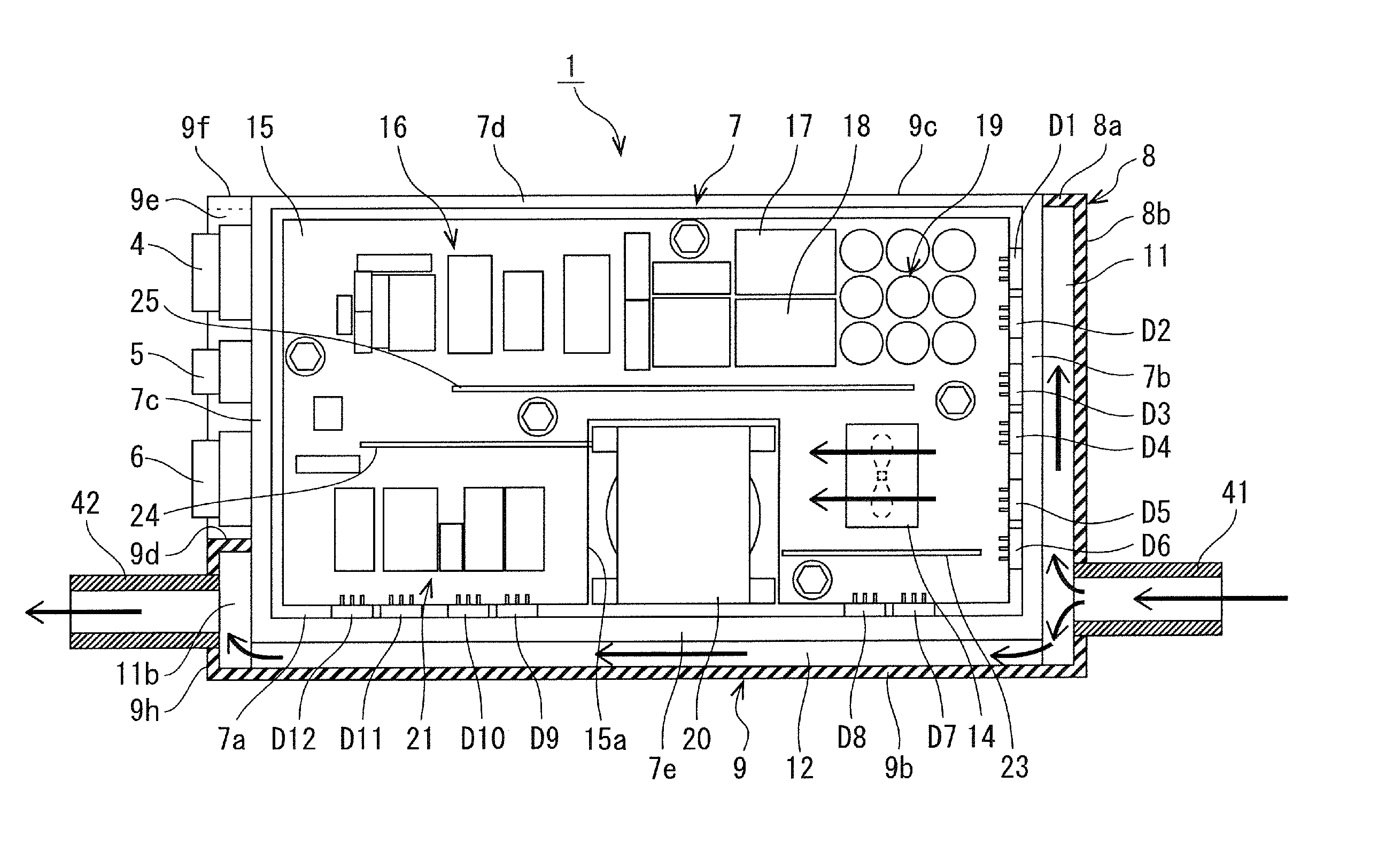
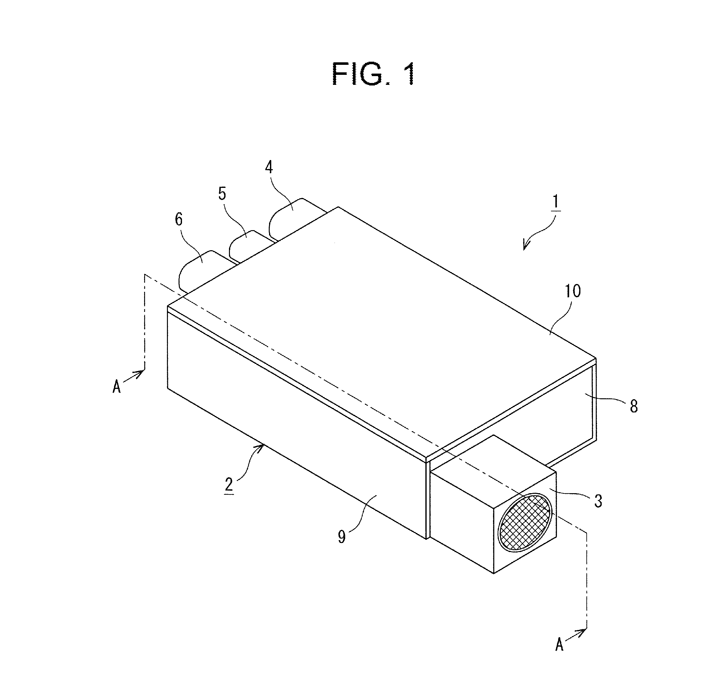
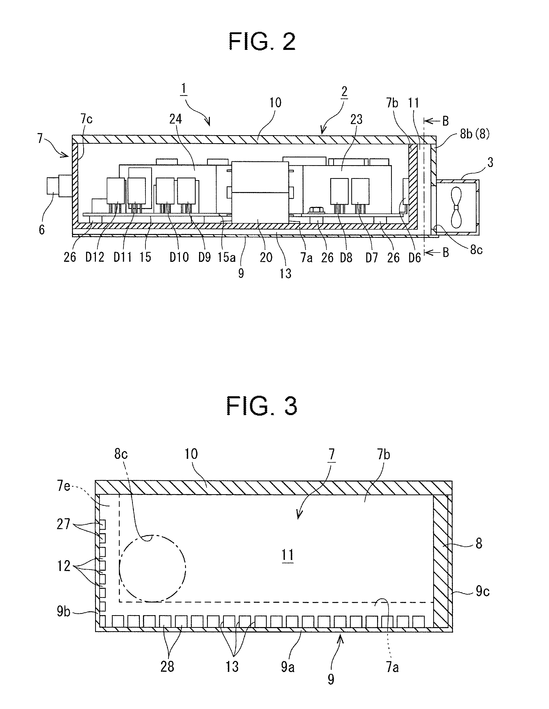
[0038]As illustrated in FIG. 1, a power converter 1 is a device used as an AC / DC converter and includes a rectangular parallelepiped housing 2. A blower fan 3 as a coolant supply device is externally attached to one side surface in a longitudinal direction of the housing 2. Moreover, an input connector 4, a control connector 5, and an output connector 6 are provided in parallel on the other side surface in the longitudinal direction of the housing 2. A power conversion control unit described later is incorporated in the housing 2. When a control signal is input to the control connector 5, commercial power input to the input connector 4 is converted from AC to DC by the power conversion control unit and is output as DC power from the output connector 6.

[0039]Specifically, the rectangular parallelepiped housing 2 includes a casing 7, a chambe...

second embodiment

[0079]As illustrated in FIG. 8, a power converter 1 is used for charging a battery mounted in an electric vehicle, a hybrid vehicle, or the like, for example, and includes a heat exchanger 50, a reservoir tank 60, and a pump 70 in order to circulate cooling water.

[0080]In the power converter 1, a cooling water supply port 41 and a cooling water drain port 42 are externally attached to the housing 2.

[0081]The cooling water drain port 42 is connected to the heat exchanger 50 by the drain pipe 43. The heat exchanger 50 may be an air-cooled radiator or the like mounted in a vehicle. The cooling water supply port 41 is connected to the pump 70 by a supply pipe 46.

[0082]The reservoir tank 60 storing cooling water is provided between the heat exchanger 50 and the pump 70, and the reservoir tank 60 is connected between the heat exchanger 50 and the pump 70 by pipes 44 and 45.

[0083]In the present embodiment, when the cooling water stored in the reservoir tank 60 is pressurized by the pump 7...


PUM


Abstract

A cooling device includes a plurality of side wall fins formed on an outer surface of a first side wall of a housing, and a plurality of bottom fins formed on a bottom surface of a bottom portion of the housing. A cover member covers the side wall fins and bottom fins from an outer side to form side wall and bottom cooling channels. A chamber is provided that forms a fluid introduction chamber in a direction facing a second side wall so as to communicate with the side wall cooling channel and the bottom cooling channel. A coolant supply device is externally attached to the chamber so as to supply a coolant to the fluid introduction chamber. The side wall fins and the bottom fins are formed in predetermined shapes to adjust an amount of the coolant in the side wall cooling channel and the bottom cooling channel.

Description

CROSS-REFERENCE TO RELATED APPLICATIONS[0001]This application is a continuation under 35 U.S.C. 120 of International Application PCT / JP2014 / 000922 having the International Filing Date of Feb. 21, 2014, and having the benefit of the earlier filing date of Japanese Application No. 2013-056929, filed Mar. 19, 2013. All of the identified applications are fully incorporated herein by reference.TECHNICAL FIELD[0002]The present invention relates to a cooling device that cools heat generating electronic components incorporated in a housing and a power converter having the cooling device.BACKGROUND ART[0003]A power converter such as an AC / DC converter includes a cooling device that cools down a plurality of electronic components including a heat generating electronic component, and an example of such a cooling device is disclosed in Patent Document 1, for example.[0004]The cooling device of Patent Document 1 has an electronic component such as a substrate or a semiconductor device mounted on...

Claims


Application Information

Patent Timeline
IPC IPC(8): H05K7/20
CPCH05K7/20154H05K7/20927H05K7/202H05K7/20909H05K7/20918
Inventor SAKUMA, MASAKIGEKINOZU, MASAKAZUNISHIKAWA, YUKIHIROTANAKA, YASUHITO
Owner FUJI ELECTRIC CO LTD
Why Eureka
Try Eureka