Synthetic fuel plant

Inactive Publication Date: 2006-09-26
MCNAT
View PDF8 Cites 0 Cited by
  • Summary
  • Abstract
  • Description
  • Claims
  • Application Information

AI Technical Summary

Benefits of technology

[0016]Providing a synthetic fuel processing plant on a barge or other floating base provides significant advantages over typical land-based plants. For example, coal and liquid binder such as latex are delivered to the plant by barge, and in large quantities. Processed synthetic fuel is also delivered from the plant to an energy producing site by barge. Transportation costs are low. There is no overland delivery of raw products and no resulting ground or surface water contamination.
[0018]Moreover, if an energy producer or facility fails, is closed, moves, or switches to an alternate fuel, the synthetic fuel plant according to the invention can easily be moved to serve another energy producer. Also, a single synthetic fuel plant, according to the invention, can serve more than one energy facility from one location by barge.
[0019]Accordingly, advantages provided by the invention include, but are not limited to: facilitation of EPA compliance; labor compliance; elimination of overland transportation of product; mobility; reduction or elimination of governmental permit and regulation jurisdictional problems facilitates delivery of raw products of coal and liquid binder to the synthetic fuel plant in large quantities and by cheaper transportation than overland delivery and elimination of ground and surface water contamination by dumping of coal on the ground of the synthetic fuel plant.

Problems solved by technology

Current plants producing such synthetic fuels, however, are attended by many significant problems.
This process entails heavy equipment and conveyor systems which pose both air and land environmental concerns.

Method used


Image

  • Synthetic fuel plant
  • Synthetic fuel plant
  • Synthetic fuel plant

Examples


Embodiment Construction

[0026]For purposes of the following descriptions, the terms “mined coal” and “liquid binder” have the meanings as described above.

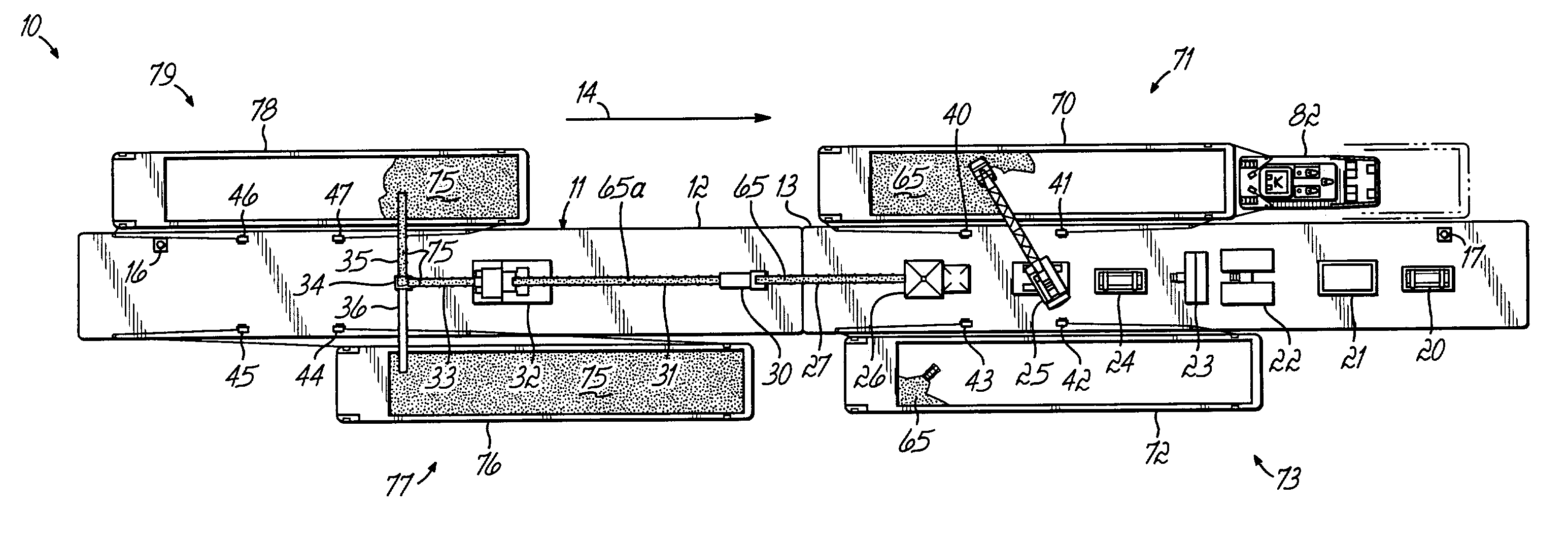
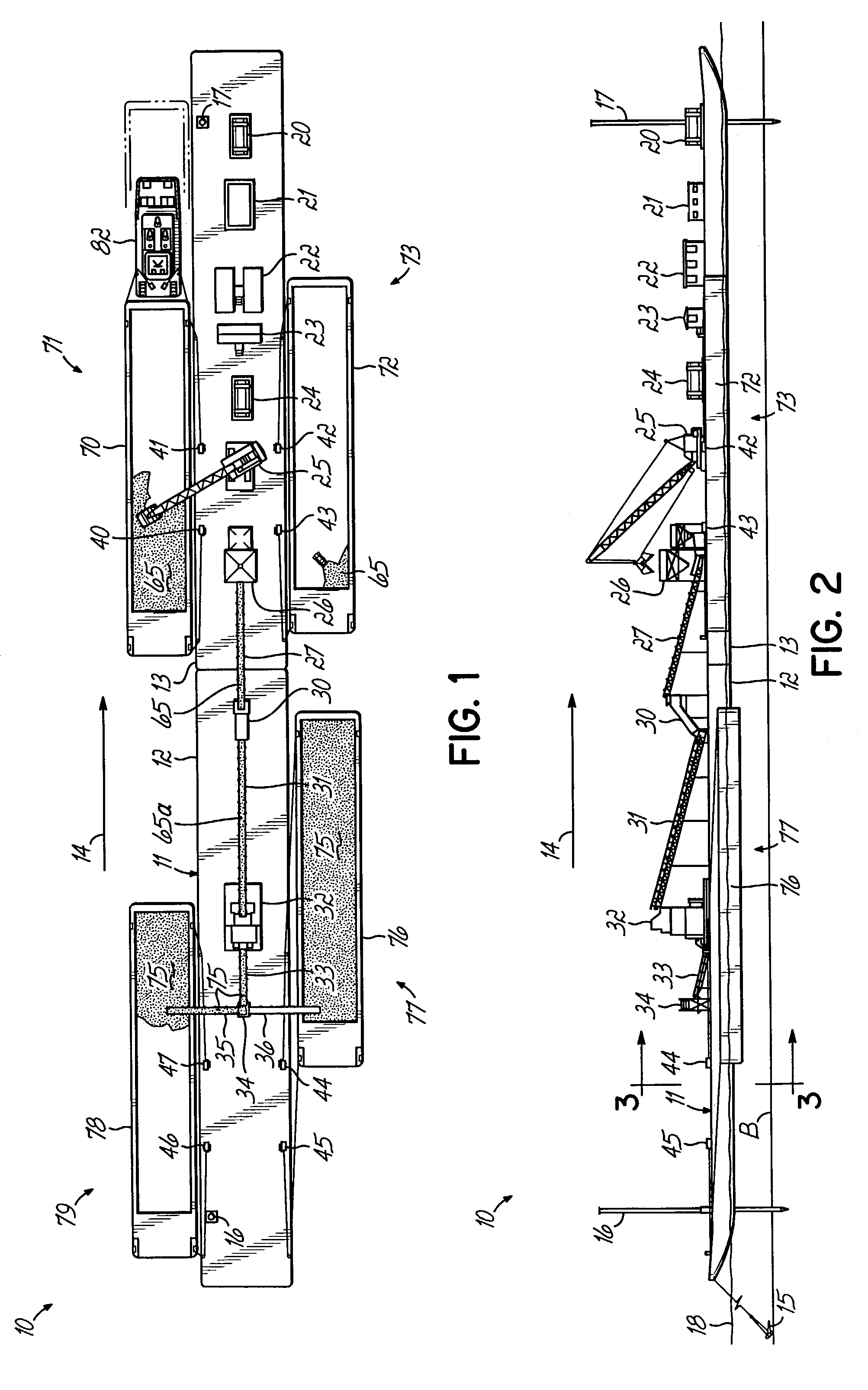
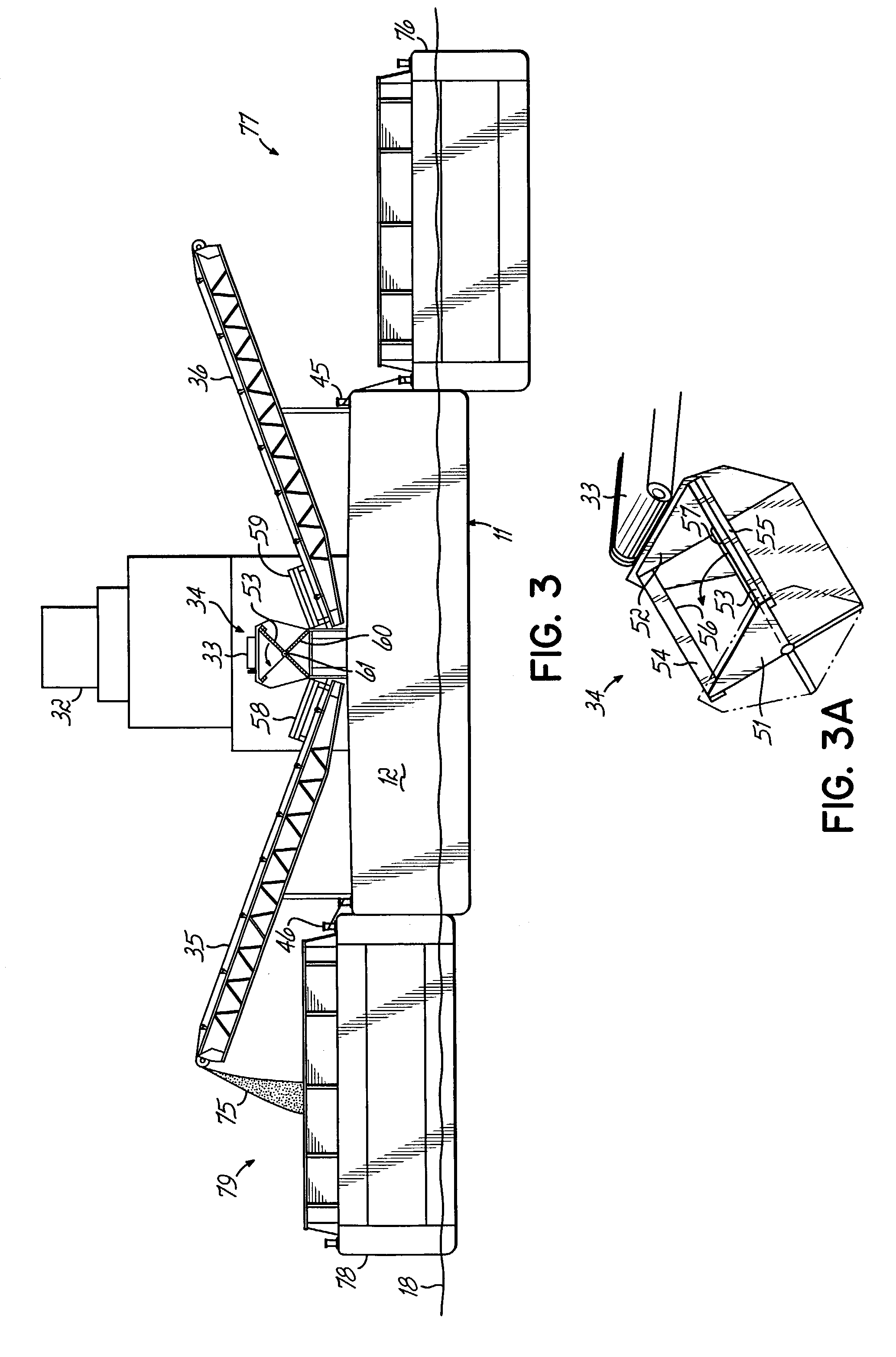
[0027]Turning now to the figures, there is shown an improved synthetic fuel plant 10 according to the invention.

[0028]Plant 10 includes an elongated floating barge 11, comprised of one or more floating barge sections, two sections being shown at 12 and 13, and each, for example, about 295 feet long. Barge 11 is free floating above waterway bottom “B” (FIG. 2), i.e. not permanently supported by pilings or such structures. Barge 111 may be tethered in place in a river or commercially navigable inland waterway, the flow 14 of which is indicated by the arrows in FIGS. 1 and 2. Such tethering may be by way of one or more anchors 15 (FIG. 2) on bottom “B” or by slidable tethers to pilings 16, 17, for example, extending up from bottom “B”. Barge 11 can rise and fall with the water level 18 (FIG. 2).

[0029]Disposed on section 13 of barge 11 are, from right to left...


PUM


Abstract

A self-contained, floating, waterway supplied and moveable synthetic fuel plant includes apparatus for receiving components of and for making synthetic fuel of coal and binder for energy consumers. Processes are disclosed.

Description

FIELD OF THE INVENTION[0001]This invention relates to the manufacture of synthetic fuel and more particularly to the manufacture of synthetic fuel (sometimes referred to as “synfuel”) preferably comprising mined coal and an approved liquid binder in an improved synthetic fuel manufacturing plant.BACKGROUND OF THE INVENTION[0002]Use of synthetic fuel comprising coal treated with liquid binder is known. There are a number of approved binders suitable for use in synfuel plants, the most popular being latex-based. Typically, mined coal is sprayed with a binder compound or mixture, optionally formed into briquets or pellets, and then delivered to the furnace of a synthetic fuel consumer such as an energy producer. Such synthetic fuel treatment plants are made, for example, by Startec, Inc. of Dublin, Ohio. Significant tax credits are available for synthetic fuel producers under strict IRS guidelines, as the product is typically more energy efficient in BTUs produced or the like.[0003]Cur...

Claims


Application Information

Patent Timeline
IPC IPC(8): B63B35/44C10L5/14
CPCB63B35/44C10L5/361C10L5/14
Inventor MCGINNIS, CHARLES DOUGLAS
Owner MCNAT
Why Eureka
Try Eureka