
System and method for integrating electrical power grid and related data from various proprietary raw data formats into a single maintainable electrically connected database

a technology of electrical power grid and data, applied in the field of sending and receiving electrical system data, can solve the problems of grid reliability and security, limited range and frequency of electrical power transfers, and difficult updating of power system equipment representation, so as to maintain confidentiality of ems-specific data formats, the effect of easy updating

Inactive Publication Date: 2006-09-19
SIEMENS IND INC
View PDF5 Cites 84 Cited by
  • Summary
  • Abstract
  • Description
  • Claims
  • Application Information

AI Technical Summary

Benefits of technology

[0036]Another advantage of the present invention is the speed of the automated process that converts the various EMS data formats into a Common Information Model. The computer processing time required to convert a vendor specific EMS raw data set into the CIM data format is significantly less than manual methods once the vendor-specific EMS conversion “filter” to the CIM has been developed.
[0037]Yet another advantage of the present invention is the ease of updating of the power systems equipment representation using a graphical user interface with various hierarchical views capable of downward tree expansion.
[0038]Yet another advantage of the present invention is the resolution of unique naming convention problems encountered when integrating foreign electrical network topologies through automatic cross-reference generation of inter-substation Tie Lines and related power systems equipment.
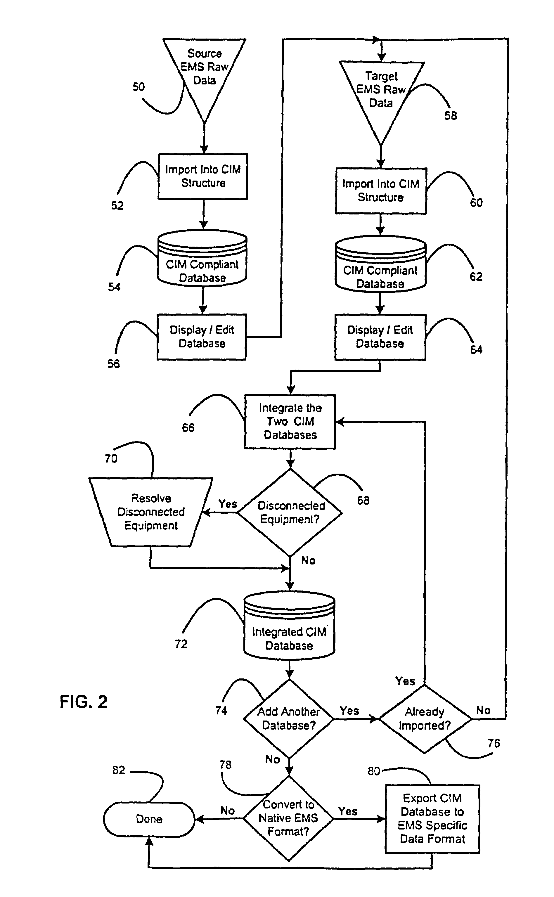
[0039]Yet another advantage of the present invention is the automatic conversion of one EMS vendor's power system data format into another EMS vendor's format while maintaining confidentiality of EMS-specific data formats.
[0040]Still another advantage of the present invention is the automated integration of multiple EMS vendors' power systems databases, or portions thereof, into a single electrically connected database.
[0041]It is therefore an object of the present invention to provide a method and apparatus that inputs the raw data from any EMS data format and automatically converts it into the CIM structure with specific integration extensions.

Problems solved by technology

Transferring power outside of the limited geographical area containing detailed electrical network models is problematical simply because of the lack of a unified network model.
Consequently, such electrical power transfers are very limited in their range and frequency.
Without this fundamental model information (which does not exist), grid reliability and security is at risk and dependable market trading is impaired.
Keeping models up to date will become an even more demanding task when the North American Electric Reliability Council (NERC) policy on exchange of real-time network data is deployed on Sep. 1, 2001.
The present state of the art is such that sending or receiving electrical power data and models from different EMS vendors is difficult at best to perform without significant advance notice.
The lack of a detailed power system network topology when spanning two or more EMS vendor data formats can result in electrical power scheduling failures.
The scheduling error occurs when company B attempts to send power through the same lines that are already in use by companies A and C. This case is not rare, but is risky since company B does not model A or C to determine the effect of the transfer in company B.
Generally, at least 24 hours advance notice is required by any given EMS vendor to send or receive electrical power to a different EMS due to the problems associated with scheduling dynamic balancing between the generation capacity and demand load for a given time interval starting from different data formats.
This time period can be a significant limiting factor in the case of an unpredictable emergency caused by natural phenomena such as a hurricane or unusually high temperatures during the summer months.
There is a lack of instruction on how to convert various data formats into the CIM structure and further a lack of instruction on how to merge data from multiple CIM compliant databases.
However, these relationships have inherent limitations that must be expanded in order to produce and maintain composite network models as described herein.
A database capable of recalling specific power systems equipment requires significant programming effort simply because of the vast amount of equipment involved and the numerous types of equipment to be classified.
Electrical power transfers are generally limited to about 1000 miles due to the degradation of electrical flow though the wires.
Combining these models currently requires extensive manual effort to ensure that the electrical connections are correct and properly electrically terminated.
None of the current EMS vendors have converted their proprietary power systems data to the CIM structure.
Another instance of naming convention problems is when power utility companies merge with bordering companies having the same or different EMS data formats.
The company network topologies must be combined and again, unique naming of the power systems equipment presents the problem even when the newly acquired utility has the same EMS format.
Yet another example of naming convention problems is when one EMS vendor allows duplicate names for specific power systems equipment and this is an error condition in the foreign EMS vendors' system.
Consolidating the 16 or more character names into an eight-character field presents additional naming problems.
Modeling is generally sparse in terms of the power system equipment detail for the target network topology due to the limited information provided by the target company and the proprietary nature of the EMS in the target substation.
This is labor intensive again due to the requirement that the resulting combined network topology must have proper connectivity.
This problem is further compounded by the modeling efforts of the source substation's sparse representation of the target substation's network.
EMS vendors do not provide the same level of detail for all of the power systems related equipment.
The manual effort required to generate a fully populated network topology is monumental when there are no starting references other than the application programs controlling the power flow.
Obviously, these methods are time consuming and prone to human error.

Method used


Image

  • System and method for integrating electrical power grid and related data from various proprietary raw data formats into a single maintainable electrically connected database
  • System and method for integrating electrical power grid and related data from various proprietary raw data formats into a single maintainable electrically connected database
  • System and method for integrating electrical power grid and related data from various proprietary raw data formats into a single maintainable electrically connected database

Examples


Embodiment Construction

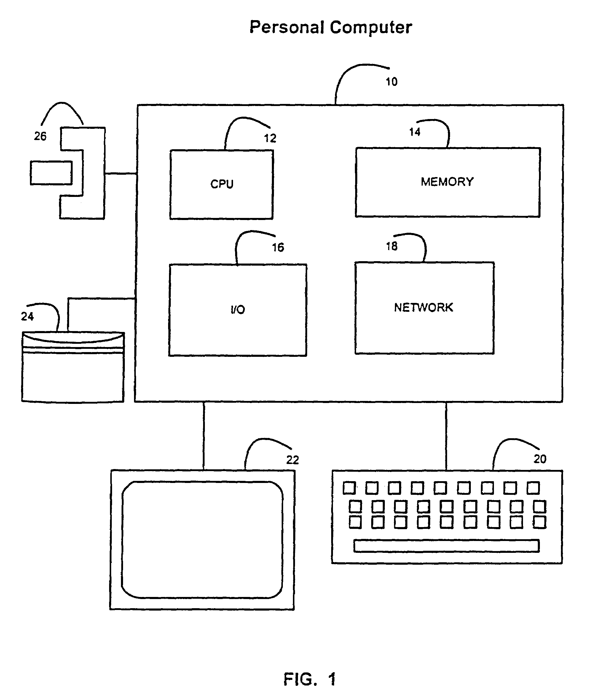
[0095]In FIG. 1, there is shown a block diagram of the internal components of a personal computer 10 upon which the present invention can be practiced. A computer 10 has a central processing unit (CPU) 12. In the preferred embodiment, the CPU is an Intel Pentium microprocessor, although the present invention can be used with other microprocessors as well. A CPU 12 is connected to a Memory 14. A memory 14 is typically the newer Synchronous Dynamic Random Access Memory or the older Dynamic Random Access Memory configured in Single Inline Memory Modules (SIMM). A CPU 12 is also connected to an I / O Controller 16 that is in turn connected to a Keyboard 20 and Display 22. Network 18 interface card is a common addition to many personal computers and is also connected to a CPU 12. Mass Storage Device 24 and removable media device 26 are similarly connected to a CPU 12. The present invention can be implemented on other types of computers besides a computer 10 shown and described in FIG. 1.

Ov...


PUM


Abstract

An improved system and method of automating the integration of different Energy Management Systems (EMS) electrical power grid databases into a single power grid database. This method imports proprietary EMS raw data from various vendors' formats into a Common Information Model (CIM) with specific connectivity extensions and produces an electrically connected power systems database that can be viewed or edited. Direct network topology conversion from one EMS vendor data format to another is also supported. Two generated databases can then be selectively integrated and maintained to produce a fully populated network topology without disclosing EMS vendor specific proprietary information. The new, possibly larger, database can then be added to yet another database that is similarly processed.

Description

CROSS REFERENCE TO RELATED APPLICATIONS[0001]This application is a continuation of U.S. patent application Ser. No. 09 / 702,150, entitled “System and Method for Integrating Electrical Power Grid and Related Data from Various Proprietary Raw Data Formats into a Single Maintainable Electrically Connected Database,” by Margaret E. Goodrich, Jeffrey S. Peterson, David B. McClendon, and Kevin B. Perry, filed Oct. 30, 2000, now U.S. Pat. No. 6,516,326 which application is hereby incorporated by reference herein.BACKGROUND OF THE INVENTION[0002]1. Technical Field of the Invention[0003]The present invention relates to the sending and receiving of electrical system data between different Energy Management Systems (EMS). Currently, there are approximately one dozen large EMS vendors and many small vendors. Each EMS vendor data format is inherently incompatible with any other EMS data format. More particularly, the present invention relates to an automated system and method to integrate, conver...

Claims


Application Information

Patent Timeline
Patent Type & Authority Patents(United States)
IPC IPC(8): G06F17/00G06F17/30
CPCG06F17/30566Y10S707/99943Y10S707/99945Y10S707/99948Y10S707/94Y10S707/99942G06F16/256
Inventor GOODRICH, MARGARET EPETERSON, JEFFREY SMCCLENDON, DAVID BPERRY, KEVIN B
Owner SIEMENS IND INC
Learn More