
Radio communication apparatus, radio base station, radio network controller, and transmission power control method

a radio communication apparatus and radio network controller technology, applied in power management, multiplex communication, wireless communication, etc., can solve problems such as inability to receive in the signaling state, problems that are usually generated, and far-near problems, and achieve the effect of reducing durability and high durability

Inactive Publication Date: 2013-11-12
FUJITSU LTD
View PDF17 Cites 0 Cited by
  • Summary
  • Abstract
  • Description
  • Claims
  • Application Information

AI Technical Summary

Benefits of technology

[0110]In one embodiment of the present invention, a transmission power control method for controlling target quality of the received signal used for inner loop transmission power control with outer loop transmission power control, comprises the steps of detecting a change in durability for transmission error of the received data, and executing an update of the target quality, when higher durability is detected through the detecting process, slower than update of the target quality when lower durability is detected through the detecting process.

Problems solved by technology

In this case, since distance between the user equipment 4 and the radio base station 3 may be changed significantly in some cases, a far-near problem, for example, is generated.
However, a problem is usually generated when the outer loop transmission power control is executed on the basis of the data which allows change of the encoding rate.
Therefore, excellent error quality can be calculated with the second reception quality calculator 14, resulting in a similar problem.
Moreover, even in the single-call state in place of the multi-call state, if the target value of the first reception quality is lowered because the non-signaling state is continued in the audio data, a problem is also generated, in which reception fails in the signaling state.

Method used


Image

  • Radio communication apparatus, radio base station, radio network controller, and transmission power control method
  • Radio communication apparatus, radio base station, radio network controller, and transmission power control method
  • Radio communication apparatus, radio base station, radio network controller, and transmission power control method

Examples


first embodiment

[0126][a] First Embodiment

[0127]In the first embodiment, changes in durability for transmission error (for example, changes in coding rate and number of divisions or the like) are detected and the transmission power control (outer loop transmission power control) is executed in accordance with the result of detection.

[0128]The structure of the basic mobile communication system utilizes a structure of the WCDMA (UTRA FDD) mobile communication system shown in FIG. 1. It is also possible to introduce a change in which a part or the entirety of the functions of the radio network controller RNC 2 and the radio base station 3 are integrated into a node.

[0129]Moreover, for the frame structure of the up-link, the data size of audio communication, and TFCI, those similar to that shown in FIG. 3 to FIG. 6 may be employed.

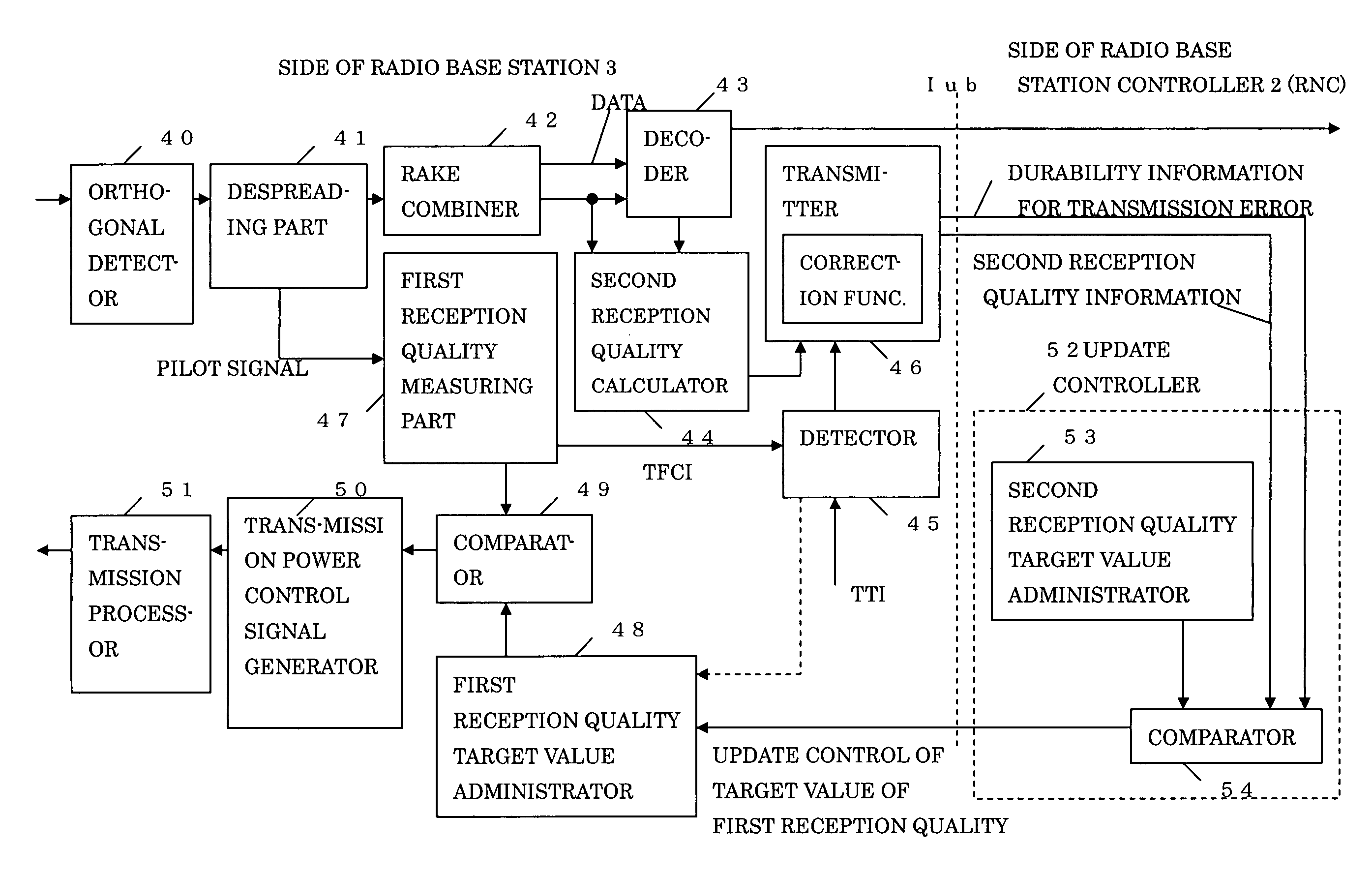
[0130]FIG. 8 shows a structure of the apparatus for executing transmission power control (for up-link) in relation to this embodiment.

[0131]A radio communication apparatus ma...

second embodiment

[0192][b] Second Embodiment

[0193]In this embodiment, a correction function can be provided to the transmitter 46.

[0194]Namely, the transmitter 46 acquires the measured second reception quality from the second reception quality calculator 44 and also acquires the durability information from the detector 45 to compensate for the second reception quality information based on the durability information.

[0195]For example, when durability is high, the second reception quality is corrected to a lower level to indicate that error quality is bad.

[0196]The transmitter 46 controls the outer loop control slower by transmitting the corrected second reception quality to the side of the radio network controller 4 slower than control based on the actual error quality directly.

[0197]The comparator 45 performs, without particular attention to durability, the update control of the target value (target SIR) of the first reception quality in accordance with the comparison of the corrected second recepti...

third embodiment

[0200][c] Third Embodiment

[0201]In this embodiment, the durability information is applied to the first reception quality target value administrator 48.

[0202]The transmitter 46 transmits at least the second reception quality calculated by the second reception quality calculator 44 to the side of the radio network controller 2, but is not required to transmit the durability information.

[0203]On the other hand, the first reception quality target value administrator 48 acquires the durability information from the detector 45 and executes, even when low durability is indicated, slow update of the target value of the first reception quality when high durability is indicated.

[0204]Namely, the update control is performed with the update controller 52 without consideration of durability. However, when the acquired durability information indicates that durability is high, the slow update control is performed as in the case where the update width is narrowed for notification from the radio net...


PUM


Abstract

To enable transmission power control (outer loop control) considering changes (for example, changes in encoding gain and number of diffusions or the like) in durability for transmission error.The radio communication apparatus for controlling a target quality of a received signal used for the inner loop power control with outer loop power control. The radio communication apparatus comprises a detector operable to detect a change in durability for transmission error of received data and an update controller operable to execute a gradual update of the target quality for detection of high durability, when the detected durability is low.

Description

CROSS REFERENCE TO RELATED APPLICATION[0001]This application is related to and claims priority to Japanese Application No. 2004-263081 filed Sep. 9, 2004 in the Japanese Patent Office, the contents of which are incorporated by reference herein.BACKGROUND OF THE INVENTION[0002]1. Field of the Invention[0003]The present invention relates to an apparatus for transmission power control in a mobile communication system, and a transmission power control method. This apparatus and method can suitably be adapted to an outer loop transmission power control in a mobile communication system which employs the CDMA (Code Division Multiple Access) system such as the W-CDMA (UTRA FDD) system.[0004]2. Description of the Related Art[0005]FIG. 1 illustrates a structure of a conventional mobile communication system.[0006]Mobile communication systems conforming to various systems have been proposed and an example of the W-CDMA (UTRA FDD) mobile communication system will be described here.[0007]In FIG. ...

Claims


Application Information

Patent Timeline
Patent Type & Authority Patents(United States)
IPC IPC(8): H04B1/707H04B1/712H04J13/00H04L1/00H04W52/04H04W52/12
CPCH04W52/12H04W52/20H04W52/44H04W52/26H04W52/241
Inventor SHINOZAKI, ATSUSHI
Owner FUJITSU LTD
Learn More