
Coding symbology and a method for printing same

a technology of coding and symbology, applied in the field of coding symbology, can solve the problems of increasing scrap rate, affecting patient safety, and requiring several hours or even days to manufacture, so as to reduce potentially patient safety errors

Inactive Publication Date: 2006-09-19
BAXTER INT INC
View PDF77 Cites 39 Cited by
  • Summary
  • Abstract
  • Description
  • Claims
  • Application Information

AI Technical Summary

Benefits of technology

[0020]The present invention provides a novel identification system and a method for employing the system. The identification system can be used to control inventory, to track a patient's billing, to monitor particular dosages, to reduce potentially patient safety errors when used in combination with other safety systems possibly not yet employed and those as described in U.S. Pat. Nos. 6,139,495; 6,032,155; 5,845,264; and 5,700,998 which are incorporated by reference as though fully set forth herein, and to accomplish innumerable other means and methods.

Problems solved by technology

One problem is that the die has sharp edges that oftentimes damage the flexible substrates heretofore mentioned, thus increasing the scrap rate.
Still yet another problem is that the hot-stamp die is costly to produce, taking several hours, or even days, to manufacture.
Accordingly, a hot-stamping system is unsuitable for printing images representative of variable information such as lot numbers, batch numbers, expiration dates or any other data that changes in a fixed time period, such as by the minute, hour, or day.
Naturally, this increases costs and decreases production rates, as well as opens the possibility for the label(s) to fall off of the product.
Several other problems exist with the hot-stamping system as it relates to the readability of the bar codes on flexible, transparent containers such as those commonly used in the medical industry.
The first problem with the readability of images printed by the hot-stamping system is that the transparent (light-absorbing) nature of the containers in such systems requires that a solid (light-reflecting) background block be printed on the container before the dark (light-absorbing) lines of the bar code can be printed thereon.
Not only is there the increased cost associated with two printing passes to achieve the two colors, but it is also fundamentally difficult to print a solid background block using the hot-stamping method because air pockets commonly form in the ink, which cause voids in the block, resulting in an unreadable bar code.
Additionally, because the background block naturally requires more pigment or ink than the contrasting bars, there is an increased risk for pigment extractives and leachables to exist in the container's solution.
A second problem is that because the hot-stamping system uses variable heat, variable pressure, and a fixed dwell time to transfer images or bar codes onto the substrate, there is a problem of the ink bleeding or growing too thick, which causes an unreadable bar code or poor edge definition of the bar code symbology.
Both solutions, however, increase costs and decrease productivity.
A third problem is that the inks in a hot-stamping system are designed to adhere to the underlying substrate, and not each other, further contributing to an unreadable bar code and mandating the development of inks that adhere to each other.
Notwithstanding the advantages of a one-color system, the remaining aforementioned problems with the hot-stamping system still exist, including the inability to print fixed and variable information in a single printing pass.
Conversely, the size and resolution limitations of the hot-stamping method force one to print fixed information on one side of the container and variable information on the other side.
These limitations add the manipulation of turning the container over and running a second printing pass, which in turn, increases costs and decreases productivity.
Notwithstanding, there still exists the problem of printing in a single pass a high resolution, one-color bar code that contains both fixed information and variable information.

Method used


Image

  • Coding symbology and a method for printing same
  • Coding symbology and a method for printing same
  • Coding symbology and a method for printing same

Examples


examples

1. Coding Symbology with a Single Bar Code

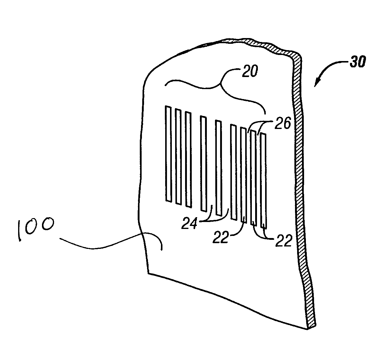
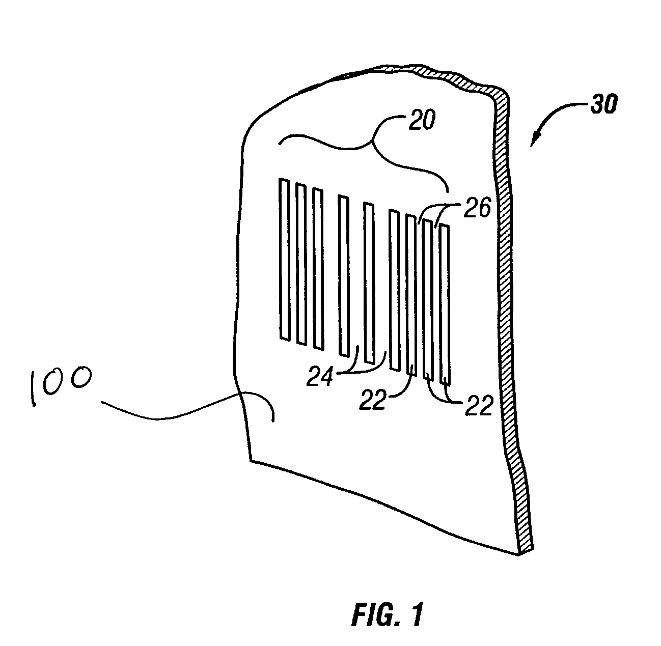
[0048]As stated above, the identification system of the present invention provides a coding symbology disposed on a substrate. The invention further provides that a plurality of light-reflecting segments, which are separated by spaces, is disposed on the substrate. The unmolested area of the substrate beneath the light-reflecting segments defines light-absorbing segments. Together, the light-reflecting segments and the light-absorbing segments define an image of a bar code. In a preferred form of the invention, the light-reflecting segments and the light-absorbing segments define a negative image of a bar code.

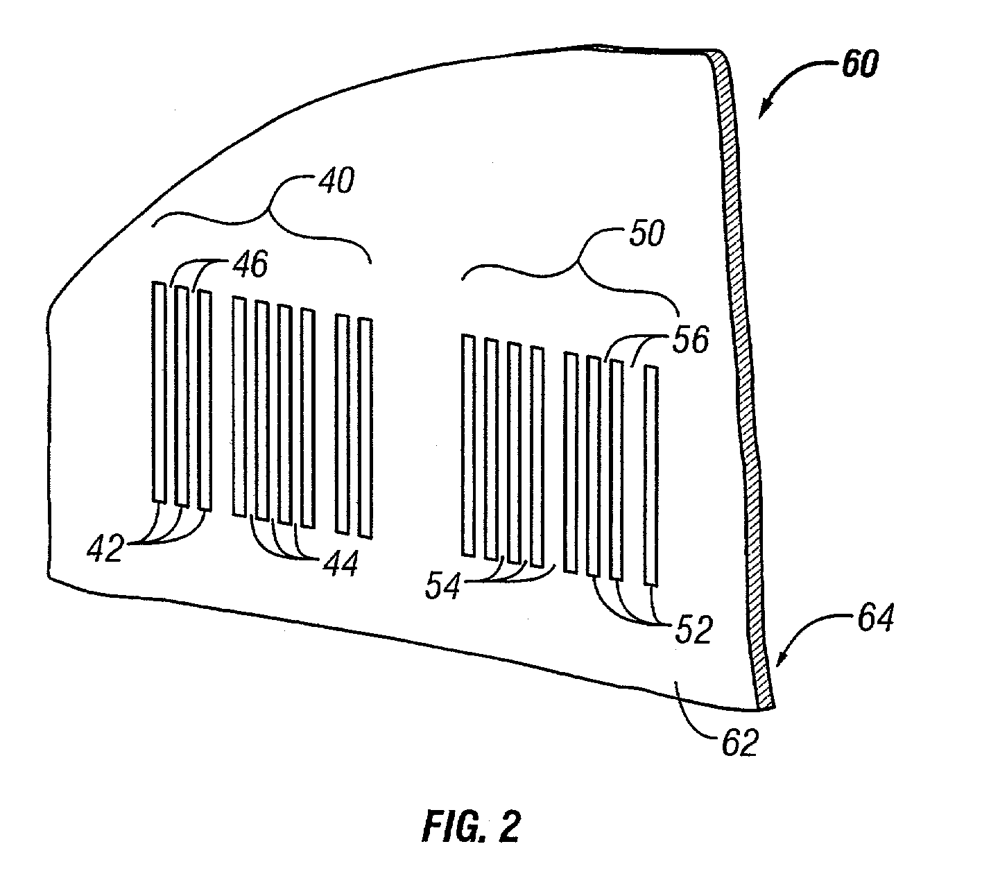
2. Coding Symbology with Two or More Bar Codes

[0049]When a second bar code is used, it is formed in the same general manner as the first bar code. That is, a second plurality of light-reflecting segments, which are separated by spaces, is disposed on the substrate. The unmolested area of the substrate beneath the light-reflecting segme...


PUM

PropertyMeasurementUnit
Temperatureaaaaaaaaaa
Lengthaaaaaaaaaa
Lengthaaaaaaaaaa

Abstract

The present invention includes forming a coding symbology by disposing a plurality of light-reflecting segments separated by spaces on a substrate. The coding symbology represents fixed information and variable information.

Description

CROSS REFERENCE TO RELATED APPLICATION[0001]This application claims priority to copending U.S. Provisional Application entitled “Coding Symbology and a Method for Printing Same”, having serial No. 60 / 280,073, filed Mar. 30, 2001, which is entirely encorporated herein by reference.DESCRIPTION[0002]1. Technical Field[0003]The present invention relates to a coding symbology containing fixed information and variable information, as well as a method for transferring same. The invention is especially suitable for flexible, transparent thermoplastic containers of liquid products that are commonly used in medical procedures.[0004]2. Background of the Invention[0005]Various foodstuffs, liquids, and other substances can be sterilely packaged in pouch-type flexible containers made from webs of flexible film, sheet stock, or like material that is sealed together along the peripheral edges. There are a number of advantages to these pouch-type flexible containers, including low weight, durability...

Claims


Application Information

Patent Timeline
IPC IPC(8): G06K7/10G06K7/00B41M3/14B41M5/382G06K1/12G06K19/06
CPCG06K1/126G06K19/06056G06K19/06009G06K19/06046G06K7/1434B41M3/14B41M5/382G06K1/12
Inventor MASE, JOSEPH C.TRINIDAD, MARGARETEDWARDS, SCOTT
Owner BAXTER INT INC
Learn More