
Snap-in facia border

Inactive Publication Date: 2006-09-12
VERSATILE PREMIUM PRODS
View PDF36 Cites 22 Cited by
  • Summary
  • Abstract
  • Description
  • Claims
  • Application Information

AI Technical Summary

Benefits of technology

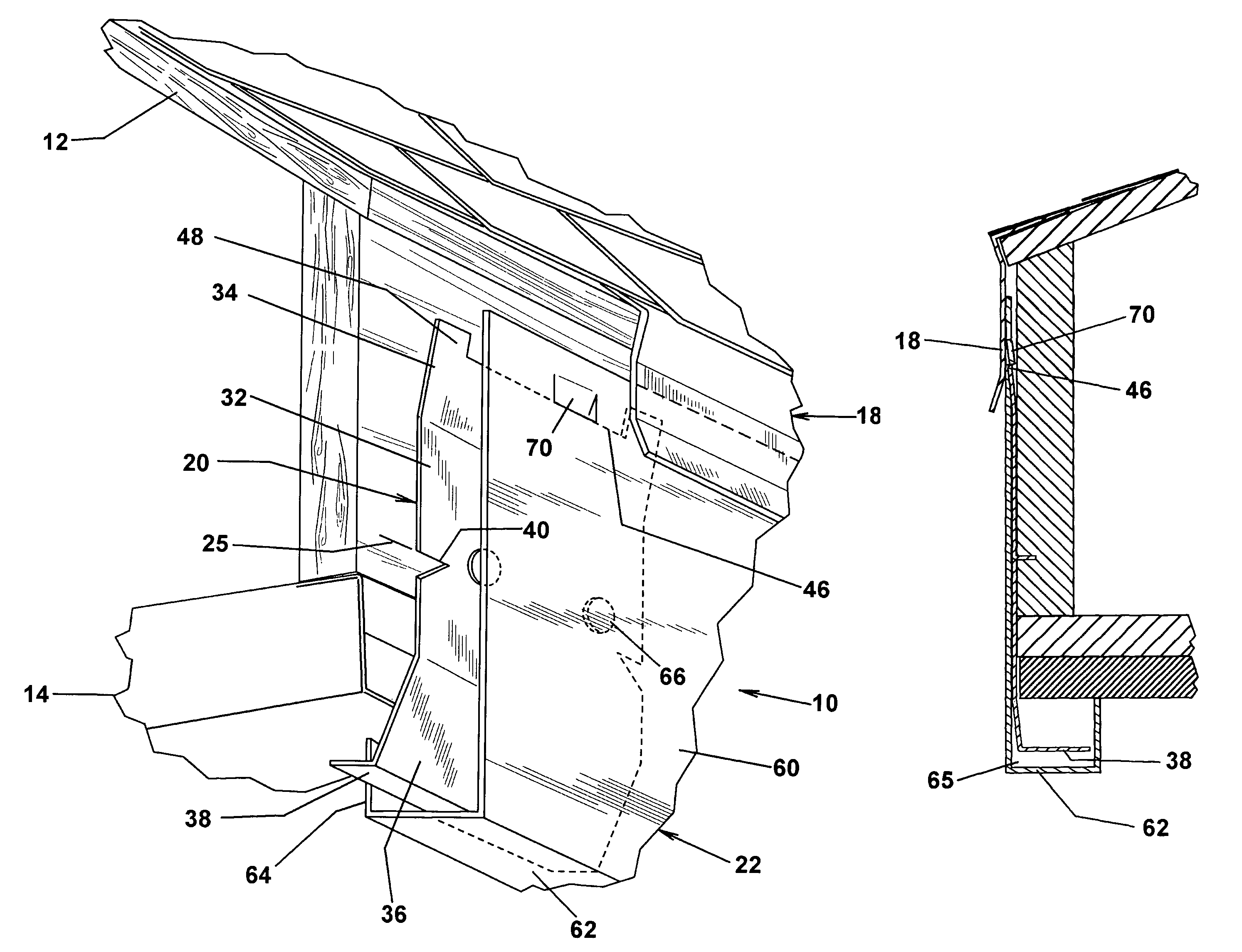
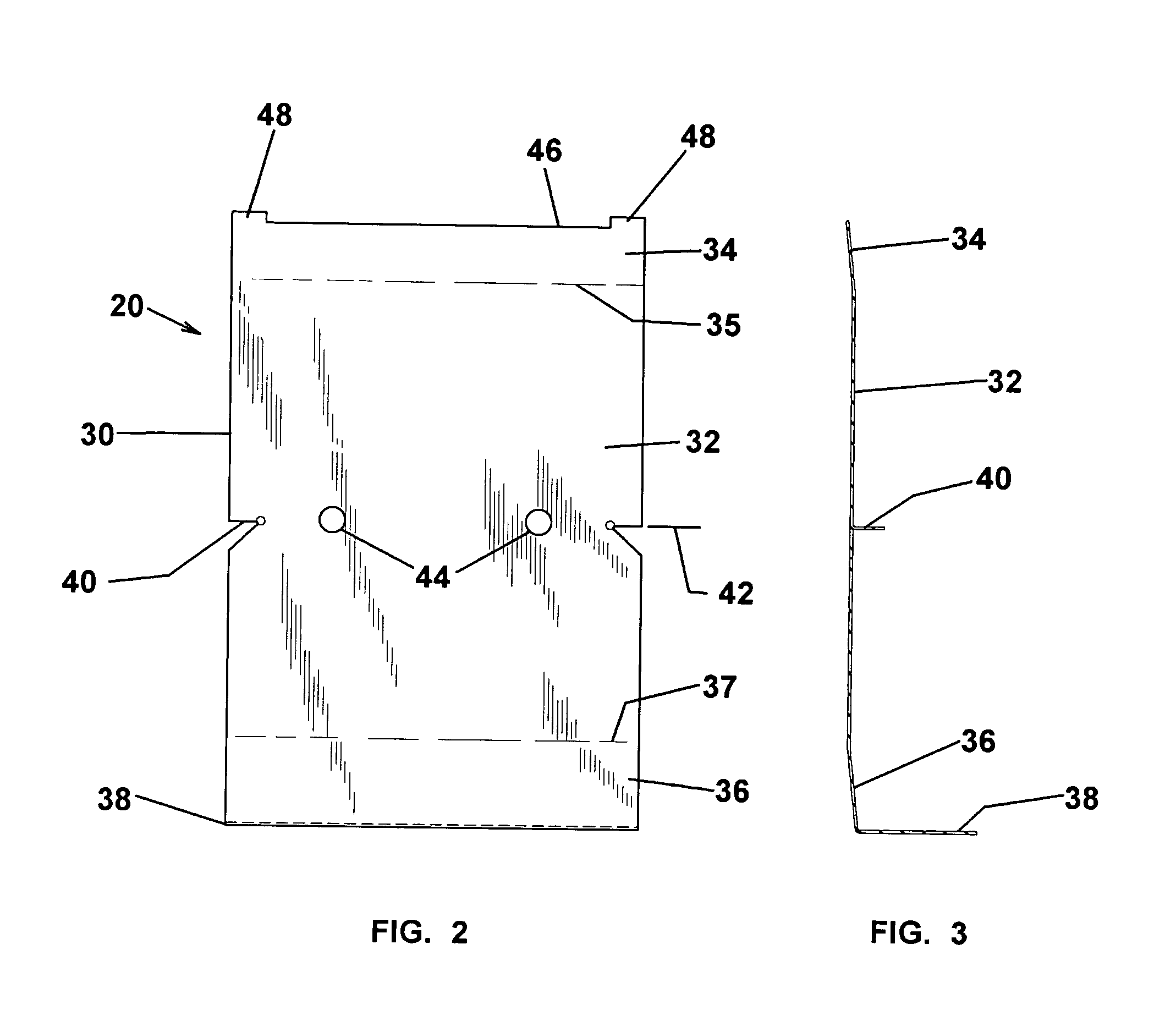
[0007]The present invention provides a snap-in facia border utilizing conventional roll formed coil trim. The facia trim is attached to mounting clips periodically spaced along the roof periphery. The mounting clips include horizontal barbs that are temporarily tacked on the nail plate along a chalk line that insures uniform positioning of the trim relative to the roof line, soffit and wall facing. After alignment, the clips are attached to the nailing plate with conventional fasteners. The upper end of the clip and an overlying leg of the roof drip edge form a pocket for receiving and retaining the upper end of the trim. The clip includes a lower leg that is slidably received in the lower trim flange for retaining the bottom of the trim. The upper end of the trim is provided with rearward swaged indentations that detent over a locating ledge on the top of the clip for limiting downward movement and locking the trim in place. The trim may be conveniently slid into the locked condition whereat the indentations detent with the locating ledge of the mounting clips, easily and with minimal dexterity. Resultantly, an accurately aligned trim using desirable standard trim components is provided.
[0008]Accordingly, it is an object of the present invention to provide a facia system for roof borders that is easy to install using conventional trim facing.
[0009]Another object of the invention is to provide a simplified method for accurately installing coil trim.
[0010]A further object of the invention is to provide a two-piece facia border for a roof periphery that is easily, accurately and securely assembled without visible fasteners.

Problems solved by technology

The advent of light weight pre-finished materials, such as aluminum trim strips, however, present installation, quality control, and decorative problems.
Because of the thin wall material commonly used, 20 gauge or less in thickness, the formed strips are prone to deflection and sagging during installation, presenting an undesirable waviness at the bottom detracting from appearance.
Unless carefully handled, the strips may also kink or buckle, further complicating installation and appearance.
Thus, unless painstakingly matched to reference markings requiring advanced carpentry skills, the finished border is irregular and decoratively compromised.
Further, the fastener installation tends to impart localized surface blemishes, in the form of dimples and waves, which are likewise unattractive.
Moreover, the rigid attachment of the trim strip presents thermal expansion problems that can produce bowings and other thermally related distortions of the trim strip.
Not entirely satisfactory attempts have been made to overcome the attachment difficulties using adhesives, however, durability and long-term adherence problems persist.
While each of the foregoing eliminates some of the drawbacks of current facia installation, custom and accordingly expensive components are required.

Method used


Image

  • Snap-in facia border
  • Snap-in facia border
  • Snap-in facia border

Examples


Embodiment Construction

[0037]Referring to the drawings for the purpose of describing the preferred embodiment and not for limiting same, FIGS. 1 and 2 illustrate a facia border 10 disposed about the periphery of a structure between a roof 12 and a soffit 14. The border may also be applied as a transition with a wall. In final assembly, the top end of the facia border 10 is commonly overlaid by a drip edge 18 or a corner molding as in other embodiments as described below. As a result, the facia border 10 forms a decorative facing for the transitions between structure walls and roofing. The facia border 10 may be used for horizontal and pitched runs.

[0038]The facia border 10 comprises a plurality of mounting clips 20 to which an elongated fascia trim 22 is slidably secured. As described in greater detail below, the clips 20 are periodically attached to a nailing plate or fascia board 24, customarily 16 inch to 24 inch on-center spacings, and longitudinally aligned with respect to a reference line 25 positio...


PUM


Abstract

A facia border for covering the periphery of a structure between the roof and a soffit includes mounting clips attached at periodic peripheral locations for slidably attaching facia trim at detented positions.

Description

RELATED APPLICATION[0001]This is a continuation-in-part application of U.S. patent application Ser. No. 10 / 198,835 filed on Jul. 22, 2002 in the name of Gates, J. Larry et al. and entitled “Facia Border”, now U.S. Pat. No. 6,751,911, issued on Jun. 22, 2004.FIELD OF THE INVENTION[0002]The present invention relates to facia borders for use around the periphery of a building roof, and, in particular, to a two-piece facia system for easy and accurate installation between the roof and soffits.BACKGROUND OF THE INVENTION[0003]Facia borders are commonly used between outer walls and roofs to provide a structural and architectural transition. Where a transition is between a soffit and the roof, an elongate strip or board is attached to the nailing plate on the outer wall and overlies the upper end thereof. A molding strip is oftentimes used to provide the final transition with the roof.[0004]The installation using lumber is well established. The material is relatively rigid and presents few...

Claims


Application Information

Patent Timeline
IPC IPC(8): E04D13/15E04D13/158
CPCE04D13/158
Inventor GATES, J. LARRYWILKINS, RONALD J.
Owner VERSATILE PREMIUM PRODS
Learn More