Power amplifier module

a power amplifier and module technology, applied in the direction of single-ended push-pull amplifiers, high-frequency amplifiers, gain control, etc., can solve problems such as thermal runaway, and achieve the effect of reducing consumption current loss and preventing damage to power amplifiers

Inactive Publication Date: 2006-09-05
PANASONIC CORP
View PDF5 Cites 5 Cited by
  • Summary
  • Abstract
  • Description
  • Claims
  • Application Information

AI Technical Summary

Benefits of technology

[0020]Therefore, an object of the present invention is to provide a power amplifier module capable of preventing a power amplifier from being damaged due to overcurrent caused by reflected power, and of reducing a loss of consumption current caused by the detection of the overcurrent.
[0022]By this configuration, it is possible to prevent the power amplifier from being damaged due to overcurrent caused by reflected power, and to reduce a loss of consumption current caused by the detection of the overcurrent. Specifically, in the power amplifier module according to the present invention, a drive current is divided among a plurality of paths. Thus, the drive current flowing through the resistor is lower than the drive current to be inputted to the power amplifier module. Hence, the voltage drop occurring in the resistor becomes smaller than that of conventional cases. Accordingly, a loss of consumption current caused by the detection of overcurrent can be reduced.
[0023]In the power amplifier module according to the present invention, a thermal element may be used as the resistance element. By this, it is possible to prevent the amplifier from causing thermal runaway. This will be described in detail below. The amplifier has properties that when used in a high-temperature environment, the amplifier causes thermal runaway and is thereby damaged at a lower current than the current at which the amplifier used in a room temperature environment is damaged. Thus, in the case where the amplifier has reached a high temperature, the switching elements need to be controlled to be in a blocking state at the time when a lower current than the current at which the amplifier used in room temperatures is damaged is detected.
[0024]For this reason, a thermal element having a negative temperature coefficient is used as the resistance element. With such a thermal element, as the temperature of the amplifier increases, the temperature around the thermal element increases, and thus the resistance value of the thermal element decreases. Hence, the magnitude of a current to be detected increases. Accordingly, the current more easily exceeds a predetermined threshold value in the control section. That is, the possibility that the switching elements are controlled to be in a blocking state is higher in a high-temperature environment than in a low-temperature environment. Accordingly, thermal runaway of the amplifier can be prevented.
[0025]By arranging a plurality of thermal elements, it becomes possible to detect temperatures at a plurality of points in the power amplifier module. This makes it possible to control the switching elements more precisely.

Problems solved by technology

The amplifier has properties that when used in a high-temperature environment, the amplifier causes thermal runaway and is thereby damaged at a lower current than the current at which the amplifier used in a room temperature environment is damaged.
Thus, in the case where the amplifier has reached a high temperature, the switching elements need to be controlled to be in a blocking state at the time when a lower current than the current at which the amplifier used in room temperatures is damaged is detected.

Method used


Image

  • Power amplifier module
  • Power amplifier module
  • Power amplifier module

Examples


first embodiment

[0048](First Embodiment)

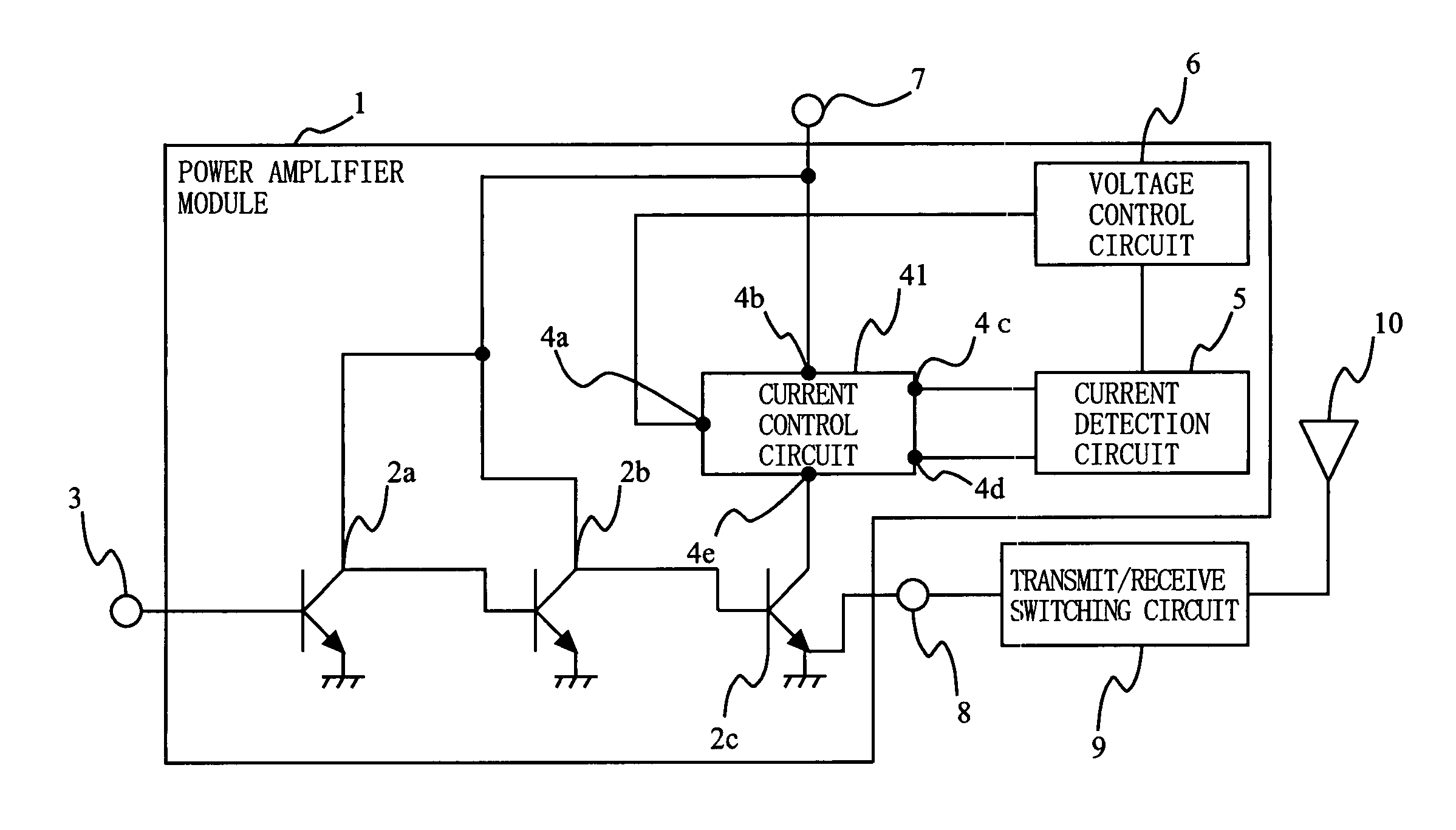
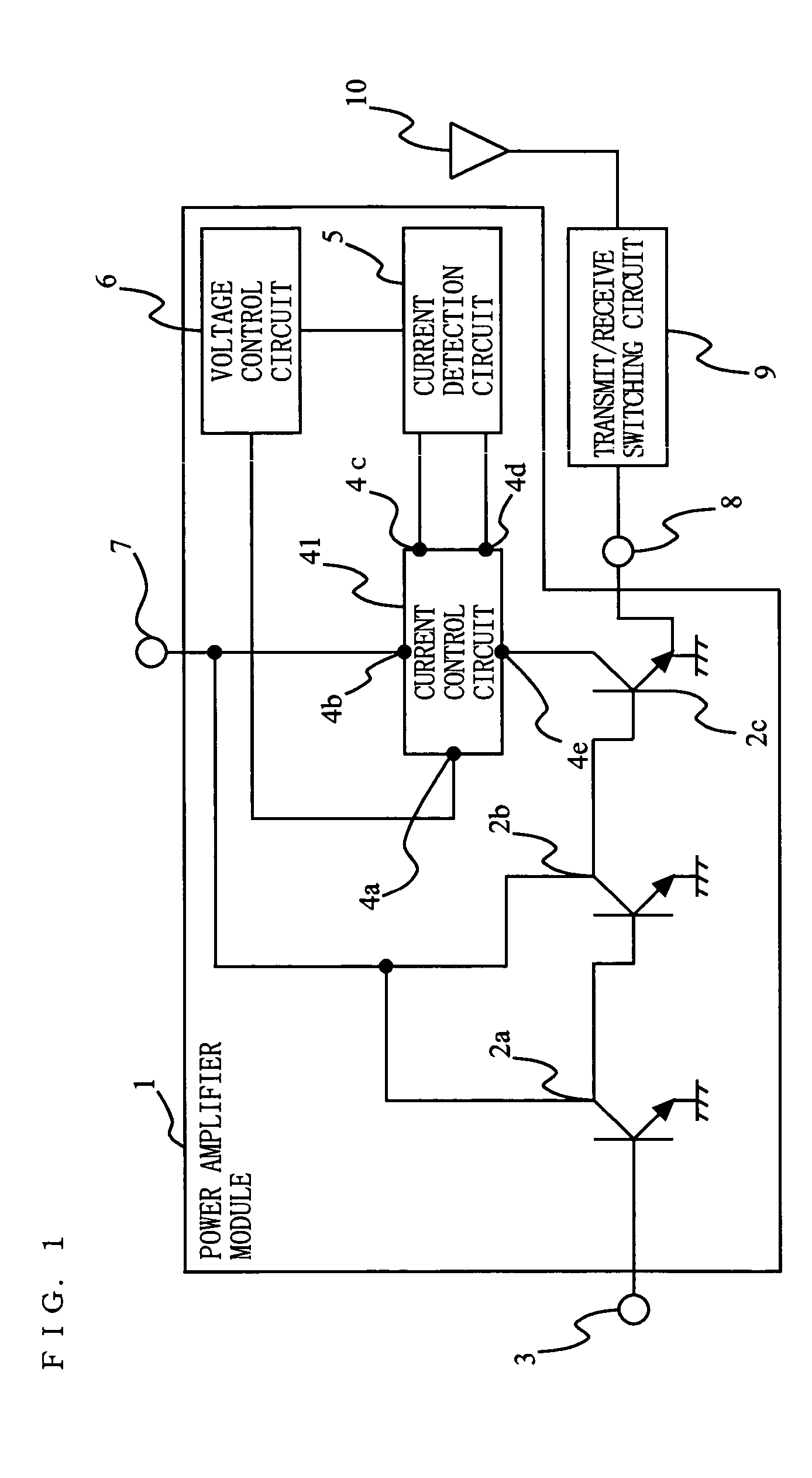
[0049]With reference to the drawings, a power amplifier module according to a first embodiment of the present invention will be described below. In order to prevent a power amplifier from being damaged due to reflected power from the antenna side, the power amplifier module according to the present embodiment has the function of detecting the magnitude of an electrical parameter, such as the consumption current of the power amplifier, and controlling the magnitude of the consumption current. Further, the power amplifier module according to the present embodiment can reduce a loss of consumption current which occurs when detecting the consumption current. FIG. 1 is a diagram illustrating a configuration of the power amplifier module.

[0050]The power amplifier module shown in FIG. 1 includes a first amplification circuit 2a, a middle amplification circuit 2b, a last amplification circuit 2c, an input terminal 3, a current detection circuit 5, a voltage control c...

second embodiment

[0075](Second Embodiment)

[0076]A power amplifier module according to a second embodiment of the present invention will be described below with reference to the drawings. The power amplifier module according to the present embodiment differs from the power amplifier module according to the first embodiment in that while in the first embodiment the last amplification circuit 2c and the current control circuit 41 are provided separately, in the present embodiment a current control function is incorporated in a last amplification circuit. FIG. 7 is a diagram illustrating a configuration of the power amplifier module according to the present embodiment.

[0077]The power amplifier module shown in FIG. 7 includes a first amplification circuit 2a, a middle amplification circuit 2b, a last amplification circuit 2d on which a current control circuit is mounted, an input terminal 3, a current detection circuit 5, a voltage control circuit 6, a power supply terminal 7, an output terminal 8, and a...

third embodiment

[0096](Third Embodiment)

[0097]A power amplifier module according to a third embodiment of the present invention will be described below with reference to the drawings. The power amplifier module according to the present embodiment differs from the power amplifier module according to the first embodiment in that while in FIG. 4 only one VR 14 is provided, in the present embodiment a plurality of VRs 14 are provided. This enables detection of temperature at a plurality of points in the power amplifier module. FIG. 10 is a diagram illustrating a configuration of the power amplifier module according to the present embodiment.

[0098]The power amplifier module shown in FIG. 10 includes a first amplification circuit 2a, a middle amplification circuit 2b, a last amplification circuit 2c, an input terminal 3, a voltage control circuit 6, a power supply terminal 7, an output terminal 8, a transmit / receive switching circuit 9, a current control circuit 51, and a current detection circuit 52. In...


PUM


Abstract

An amplifier 2c amplifies a transmit signal and outputs the amplified transmit signal to an antenna 10. A drive current for driving the amplifier 2c is inputted to a drive current input terminal 7. A current divider circuit 41 is provided between the drive current input terminal 7 and the amplifier 2c, and divides the drive current among a plurality of paths. The current divider circuit 41 includes a plurality of switching elements provided in the paths, respectively, and switched between a conduction state and a blocking state; and a resistance element 13 provided in at least one of the plurality of paths. A detection section 5 detects an electrical parameter in the resistance element. A control section 6 switches the plurality of switching elements between a conduction state and a blocking state, based on the electrical parameter detected by the detection section 5.

Description

BACKGROUND OF THE INVENTION[0001]1. Field of the Invention[0002]The present invention relates to a power amplifier module, and in particular to a power amplifier module having the function of preventing an amplifier from being damaged due to overcurrent.[0003]2. Description of the Background Art[0004]Generally, in order to emit into space a carrier wave having information superimposed thereon, a wireless apparatus includes a power amplifier module for amplifying a signal to a sufficient level; and an antenna for emitting the carrier wave.[0005]In the antenna, in order to efficiently transmit and receive signals, impedance matching is done in the transmit and receive frequency band. By thus doing matching, an output signal from the power amplifier can be emitted from the antenna. That is, reflected power is not inputted to the power amplifier module from the antenna.[0006]However, if the antenna is damaged or broken for any reason, the matching is deteriorated. As a result, part of a...

Claims


Application Information

Patent Timeline
Patent Type & Authority Patents(United States)
IPC IPC(8): H03F1/52H03F1/02H03F3/189H03F3/24
CPCH03F1/02H03F3/189H03F1/52H03F2200/366
Inventor YAMAZAKI, KAZUTAKAKATO, ICHIROKATAOKA, SHIGERU
Owner PANASONIC CORP
Why Eureka
Try Eureka