
Light source unit and wavelength stabilizing control method, exposure apparatus and exposure method, method of making exposure apparatus, and device manufacturing method and device

a wavelength stabilizing control and wavelength stabilizing technology, applied in the direction of photomechanical devices, printers, instruments, etc., can solve the problems of complicated and expensive maintenance of lasers, limited application patterns, and easy damage to optical components, and achieve the effect of sufficient accuracy

Inactive Publication Date: 2006-08-29
NIKON CORP
View PDF21 Cites 108 Cited by
  • Summary
  • Abstract
  • Description
  • Claims
  • Application Information

AI Technical Summary

Benefits of technology

The present invention provides a light source unit that generates light with a single wavelength using a light generating portion and a fiber group. The light source unit can control the amount of light emitted from each optical fiber by individually turning on / off each optical fiber in the fiber group. The light source unit can achieve a wide dynamic range and a high degree of linearity between the controlled amount of light and the light amount control is performed in stages. The fiber group can be bundled to make a compact optical element, and the light source unit can control the light output from each optical fiber by switching the intensity of pumped light from a pumping light source. The intensity of pumped light can be set to one of a predetermined level and a zero level. The technical effects of the invention include energy savings, improved light amount control, and faster on / off operation of light output.

Problems solved by technology

Up until now, issues such as improvement of the projection optical system, modified illumination, phase shift reticle have been studied and proposed, however, there were drawbacks such as the patterns suitable for application being restricted.
The excimer laser, however, has disadvantages as the light source for the exposure apparatus, such as, the size being large, the energy per pulse being large causing the optical components to damage easily, and the maintenance of the laser being complicated and expensive because of using poisonous fluorine gas.
However, since the individual laser elements were independent, fine adjustment was required in addition to an extremely complicated structure in order to make the oscillation spectrum of each laser element coincide with one another.
However, it is generally difficult to arrange the direction of the linearly polarized beams emitted from a plurality of optical fibers in order.
Also, as is well known, in the case of using an excimer laser beam in the short wavelength region, mainly due to the transmittance of the material, the material that can be used for the lens of the projection optical system at this stage is limited to materials such as synthetic quartz, fluorite, or fluoride crystal such as lithium fluoride.
In the case of using lenses made of materials such as quartz or fluorite in the projection optical system, however, correction of chromatic aberration is actually difficult.
Meanwhile, since the projection optical system is adjusted only to a predetermined exposure wavelength, if the center wavelength cannot be stably maintained, as a consequence, chromatic aberration of the projection optical system may occur, or the magnification of the projection optical system or the image forming characteristics such as distortion and focus may vary.
However, since the etalon element is affected by the temperature and pressure of the etalon atmosphere, the influence of the change in temperature and atmospheric pressure in the etalon atmosphere cannot be ignored.
In the case of such a method, however, an ND filter with a calibrated transmittance was required, and the durability of the ND filter and the change in transmittance with the elapse of time caused a problem.
Furthermore, even in the case when only 1 / 7 of the maximum exposure light amount was required, the excimer laser operated to emit the exposure light at the maximum intensity, therefore, 6 / 7 of the emitted light was not used upon exposure, and was wasted.
And, there were also difficulties on points such as the optical components wearing out and power consumption.

Method used


Image

  • Light source unit and wavelength stabilizing control method, exposure apparatus and exposure method, method of making exposure apparatus, and device manufacturing method and device
  • Light source unit and wavelength stabilizing control method, exposure apparatus and exposure method, method of making exposure apparatus, and device manufacturing method and device
  • Light source unit and wavelength stabilizing control method, exposure apparatus and exposure method, method of making exposure apparatus, and device manufacturing method and device

Examples


modified example

[0405]FIG. 7 shows a modified example of the arrangement of the light amplifying portion 161 that does not require the polarization adjustment unit or the quarter-wave plate (polarized direction conversion unit). Hereinafter, in order to avoid repetition, structures and components identical or equivalent to those described in the embodiment above are designated with the same reference numerals, and the description thereabout is briefly made or is entirely omitted.

[0406]The light amplifying portion 161 shown in FIG. 7 amplifies the pulse light emitted from the EOM160 described earlier. The structure of the light amplifying portion 161 includes: a branch and delay portion 167 which divides and branches (for example, into 128 branches) the pulse light from the EOM160C temporally and periodically; and a fiber amplifier 190 serving as a plurality of optical amplifiers.

[0407]The fiber amplifier 190 comprises: an amplifying fiber 175 arranged linearly which serves as an optical waveguiding...


PUM

PropertyMeasurementUnit
wavelengthaaaaaaaaaa

Abstract

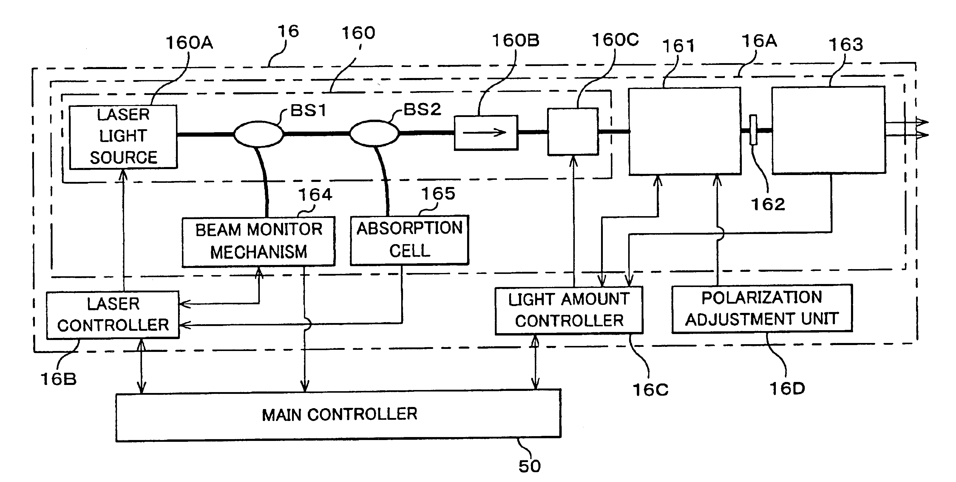
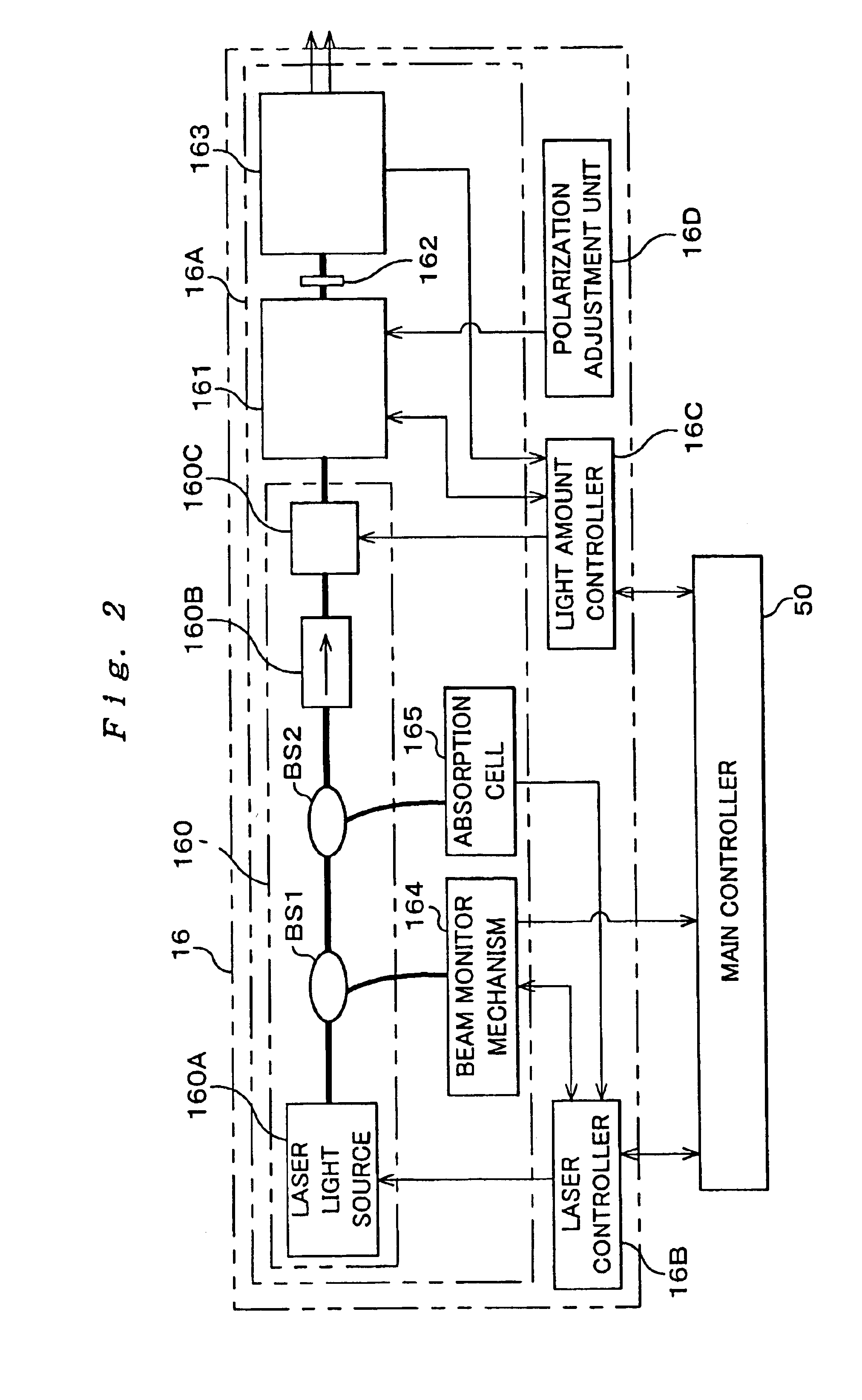
The light source unit includes a single wavelength oscillation light source, a light generating portion which has an optical modulator converting and emitting light from the light source into a pulse light, a light amplifying portion made up of an optical fiber group in which each fiber has a fiber amplifier to amplify the pulse light from the optical modulator, and a light amount controller. The light amount controller performs a step-by-step light amount control by individually turning on / off the light output of each fiber making up the optical fiber group, and a light amount control of controlling at least either of the frequency or the peak power of the emitted pulse light of the optical modulator. Accordingly, in addition to the step-by-step light amount control, fine adjustment of the light amount in between the steps becomes possible due to the control of at least either the frequency or the peak power of the pulse light, and if the set light amount is within a predetermined range, the light amount can be made to coincide with the set light amount.

Description

[0001]This application is a Continuation of application Ser. No. 09 / 831,345 Filed on Jun. 28, 2001 Now abandon, which is the National Stage of PCT / JP00 / 05875, filed Aug. 30, 2000.TECHNICAL FIELD[0002]The present invention relates to a light source unit and a wavelength stabilizing control method, an exposure apparatus and an exposure method, and a method of making the exposure apparatus, and device manufacturing method and a device. More particularly, the present invention relates to a suitable light source unit which serves as a light source for exposure in an exposure apparatus to manufacture a semiconductor device and a liquid crystal display device and the like in a lithographic process and a wavelength stabilizing control method that can be suitably applied to the light source unit, an exposure apparatus which comprises the light source unit as a light source for exposure and an exposure method using the exposure apparatus, a method of making the exposure apparatus, and a devic...

Claims


Application Information

Patent Timeline
Patent Type & Authority Patents(United States)
IPC IPC(8): G03B27/72G02F1/35G03B27/42G03B27/54B23K26/06G03F7/20H01S3/067H01S3/13H01S3/131H01S3/23
CPCB23K26/0639B23K26/0643B23K26/0648B23K26/0665G03F7/70058G03F7/70575H01S3/13H01S3/1301G03F7/70566G02F2001/354H01S3/2383H01S3/06758H01S3/1305H01S3/1312B23K26/064H01S3/13013H01S3/10015G02F1/354
Inventor OHTSUKI, TOMOKOOWA, SOICHIATSUMI, NIICHIDOI, MASAAKI
Owner NIKON CORP
Learn More