
System and method for generating three-dimensional image displays

Active Publication Date: 2006-08-29
CARL ZEISS OPTRONICS GMBH NEW NAME
View PDF17 Cites 14 Cited by
  • Summary
  • Abstract
  • Description
  • Claims
  • Application Information

AI Technical Summary

Benefits of technology

[0008]It is the object of the invention to provide a device and a method for generating three-dimensional thermal imagers which avoids the disadvantages, outlined above, of the prior art, in order in this way to acquire information on the target area to be observed which is more specific.
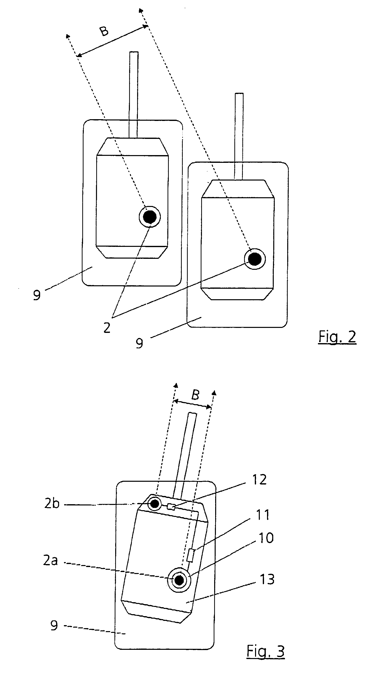
[0012]If the sensors or thermal imagers are specifically arranged in two moveable devices (vehicles) the individual images can be combined to form a stereo image given correspondence of the fields of view and parallelism of the optical axes to one another. It is particularly advantageous in this case that the relatively large basis produces a substantial stereo effect which permits good observation performance even over large target ranges.
[0016]Of course, the ability to see in three dimensions is advantageous not only with a large basis and at long ranges. The combination of the two miniaturized thermal imagers by which the implementation of a thermal imager-binoculars which affords the observer by night the advantages which are open to him during the day when using known binoculars.

Problems solved by technology

As when recording by means of two unsynchronized detectors, the disadvantage of this design resides in the fact that owing to the different recording instants, moving objects are located at slightly different points inside the partial images.
This leads disadvantageously to an undesired displacement of the moving objects in space.
It is equally to be regarded as particularly disadvantageous of the image reproduction system of DE 43 32 381 A1 that when updating the display of the stereo image after recording each partial image, the temporal relationships of the left-hand partial image to the right-hand partial image are still reversed.
If this happens, the stereoscopic viewing of the object fails.

Method used


Image

  • System and method for generating three-dimensional image displays
  • System and method for generating three-dimensional image displays
  • System and method for generating three-dimensional image displays

Examples


Embodiment Construction

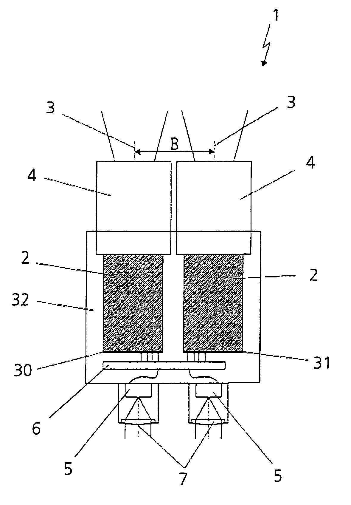
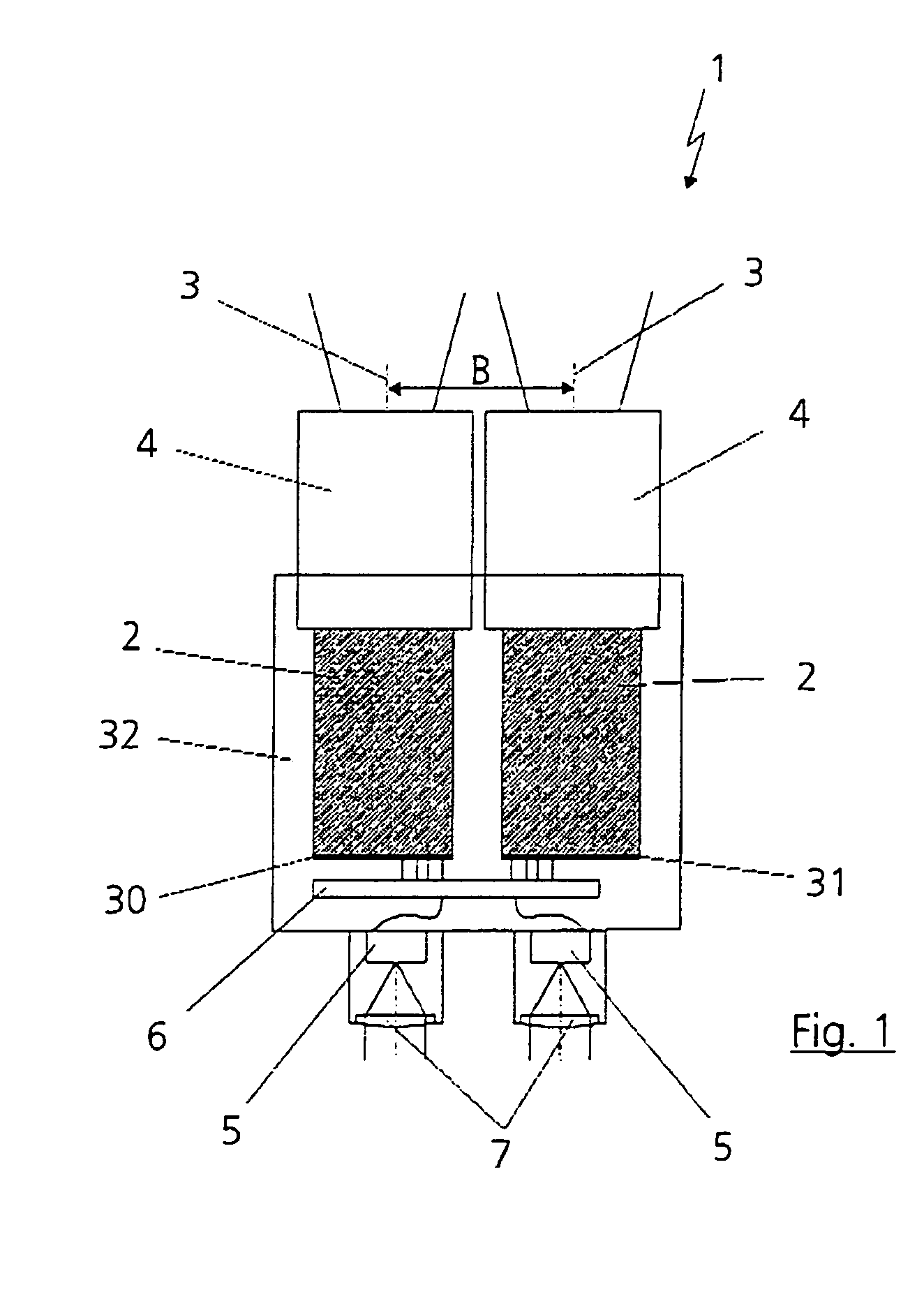
[0024]An inventive thermal imager-binoculars 1 is illustrated in outline in FIG. 1. Two miniaturized thermal imagers 2 with individual sensors, as detectors 30, 31, being sensitive to infrared radiation are combined with one another in this case. It is possible, for example, to use relatively cost-effective thermal imagers which operate with uncooled detectors. With such a handheld stereo thermal imager-binoculars 1, individual cameras with a focal length of 50 mm, for example, are arranged directly next to one another on a basis plate 32 and aligned in such a way that optical axes 3 of optics and objectives 4 of both thermal imagers 2 run parallel. This arrangement results in a stereo basis, denoted by B here, which, at approximately 100 mm, is only slightly greater than the mean interpupillary distance (PD) of approximately 64 mm. This mean interpupillary distance differs from observer to observer, however. Nevertheless, it is possible with the aid of such 50 mm objectives 4 to im...


PUM


Abstract

A system and a method for generating three-dimensional image displays with two sensors, in particular two thermal imagers, having two optical channels with fields of view of equal size and with a virtually identical line of sight has at least one image reproduction unit. The optical axes of the sensors are aligned in parallel with one another. The sensors are each provided with a detector for a stereo recording, the stereo recording being performed simultaneously by means of the detectors.

Description

CROSS REFERENCE TO RELATED APPLICATION[0001]This application relates to and claims priority to corresponding German Patent Application No. 103 25 821.3, which was filed on Jun. 7, 2003, and which is incorporated by reference herein.BACKGROUND OF THE INVENTION[0002]1. Field of the Invention[0003]The invention relates to a system and a method for generating three-dimensional image displays, in particular for generating three-dimensional thermal imagers.[0004]2. Description of the Related Art[0005]A three-dimensional display of thermal imagers has already been disclosed by DE 43 32 381 A1, in which case an image reproduction system is described which is of modular design and includes two stereo modules of identical mirror-image design. Two pairs of optics, two pairs of frame memories and two image display devices are provided for a stereo recording and a stereo reproduction. The stereo recording is performed alternately by means of only one image detector. In this case, the beam paths ...

Claims


Application Information

Patent Timeline
IPC IPC(8): G02F1/01G02B13/14G02B27/00G02B27/01G02B27/22H04N5/33H04N13/239
CPCG02B13/14G02B27/017G02B27/2228H04N5/33H04N13/0239G02B2027/0138G02B2027/0134H04N13/239G02B30/34
Inventor KUERBITZ, GUNTERSCHLEMMER, HARRYVOGEL, HOLGER
Owner CARL ZEISS OPTRONICS GMBH NEW NAME
Learn More