Front-loader dishwashing machine with heat recovery

Inactive Publication Date: 2009-02-12
MEIKO MASCHENBAU
View PDF11 Cites 20 Cited by
  • Summary
  • Abstract
  • Description
  • Claims
  • Application Information

AI Technical Summary

Benefits of technology

[0012]It is therefore an object of the present invention to provide a dishwashing machine for commercial use which avoids the disadvantages of the dishwashing machines known from the prior art and, in particular, offers a reliable, low-maintenance solution to the problem of water-vapor formation in the working environment.
[0017]The refinement according to the invention of the dishwashing machine avoids the disadvantages of the prior art as described above in that ambient air can be introduced into the dishwashing chamber, for example by means of the inlet-air fan, thus ensuring pressure equalization within the dishwashing chamber. The inlet-air channel may, in particular, be designed so as to virtually completely preclude this inlet-air channel from becoming dirty during practical use. The emergence of liquid can also be avoided by appropriate design of this inlet-air channel. By way of example, damage to sensitive items to be cleaned can be avoided by avoiding the problem of a vacuum pressure being formed within the dishwashing chamber.
[0019]In order to avoid the pressure equalization problem described above and in order to improve the reliability of the supply of ambient air, the dishwashing machine may, for example, be designed such that the fan and the inlet-air fan are operated synchronized in time. For example, an appropriate controller can be provided for this purpose, synchronizing these fans in time. In particular, this synchronization can be carried out in such a manner that the fan and the inlet-air fan are started at the same time and / or with a predetermined time offset. After the suction process, the inlet-air fan can then be stopped, for example, at the same time as or at a time before the fan. This allows the remaining vapor to be sucked out of the dishwashing chamber.
[0029]In this case, it is particularly advantageous for items to be cleaned which are accommodated in the dishwashing chamber to be finally washed in at least one final washing program step using a final washing liquid from a final washing tank. Cooling water from the condensation precipitation device can then be heated in a. subsequent suction program step by vapor and / or air from the dishwashing chamber, with the heated dishwashing water being passed into the final washing tank. This results in heat being partially recovered, and the time required for subsequent heating of the final dishwashing water can be shortened. This saves energy, and the dishwashing cycle of the dishwashing machine can be shortened further.

Problems solved by technology

In contrast to domestic appliances, dishwashing machines for commercial use are subject to the problem that the throughput times must be considerably reduced.
However, one problem with commercial dishwashing machines such as these is that, when the front door is opened, considerable amounts of vapor in. the form of water vapor can escape into the working environment, for example a large kitchen, thus considerably increasing the temperature and the air humidity in this area.
This water vapor makes the work of the operator considerably harder.
For example, operation of machines such as these by those wearing spectacles is subject to considerable difficulties.
However, in practice, this procedure is not only associated with the disadvantage of reduced throughput of plates and dishes to be cleaned, but also leads to plates and dishes that have been cleaned and dried being subjected to increased moisture as a result of vapor precipitating on the surfaces of the plates and dishes as they cool down.
However, the solution proposed in DE 10 2005 023 428 A1 has the particular disadvantage that the air supply is uncontrolled and is essentially associated with a leak in the form of a gap underneath the front door.
However, water vapor, or even liquid, can easily escape through this gap into the working environment during operation of the dishwashing machine.
Furthermore, this gap can easily become dirty thus greatly reducing the functionality of the suction process.
However, these appliances have the disadvantage that, in these appliances, the vapor is emitted directly into the working environment.

Method used


Image

  • Front-loader dishwashing machine with heat recovery
  • Front-loader dishwashing machine with heat recovery
  • Front-loader dishwashing machine with heat recovery

Examples


Embodiment Construction

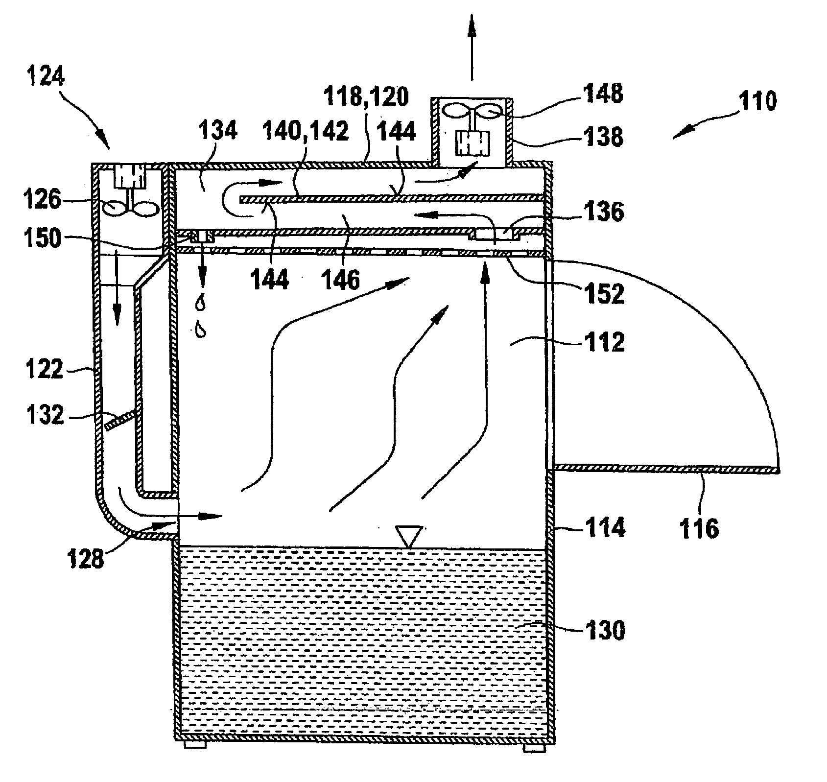
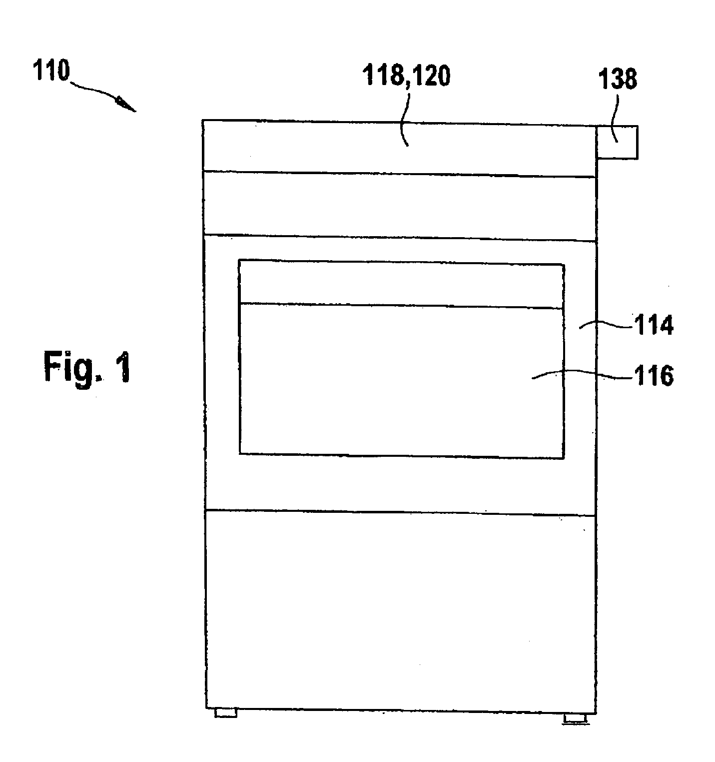
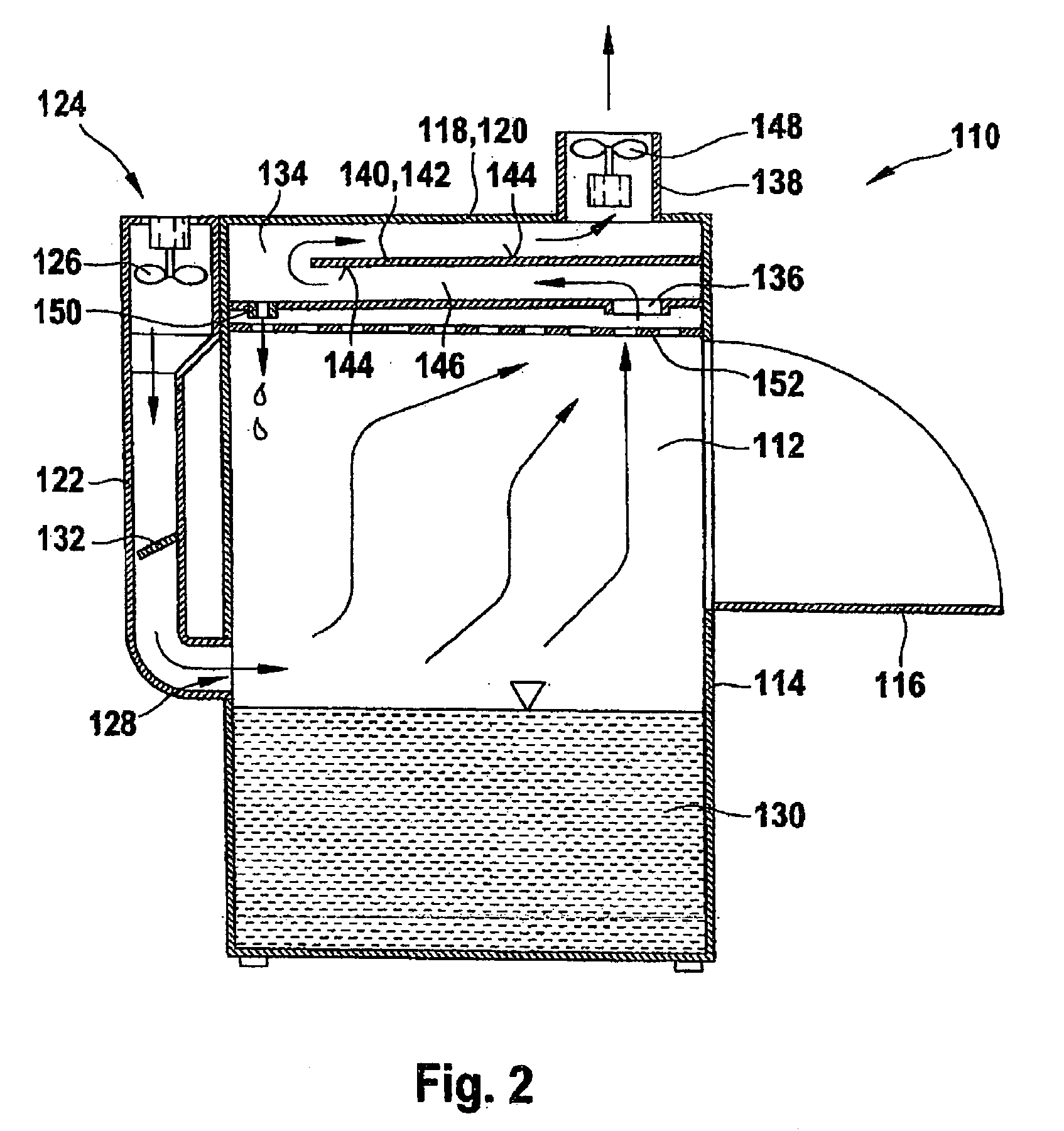
[0040]FIGS. 1 and 2 show an embodiment of a dishwashing machine 110 according to the invention, illustrated schematically. The dishwashing machine 110 is in the form of a front-loader and has a dishwashing chamber 112 with a housing 114. On its front, the housing 114 has a front door 116, which can be folded downward in this embodiment, in order to allow items to be cleaned to be loaded in the dishwashing chamber 112. This loading process can be carried out either directly, by placing items to be cleaned in appropriate holders within the dishwashing chamber 112, or this can be done by the use of baskets for the items to be cleaned. Items to be cleaned and the corresponding devices are not illustrated in FIGS. 1 and 2.

[0041]As can be seen in particular from the section illustration in the form of a side view shown in FIG. 2, the dishwashing machine 110 has a cover part 118 which is in the form of a condensation precipitation device 120. Furthermore, this exemplary embodiment of the d...


PUM


Abstract

A dishwashing machine for commercial use is provided, which has a dishwashing chamber with a front door which can be opened for loading and unloading the dishwashing chamber with items to be cleaned. Furthermore, the dishwashing machine has at least one condensation precipitation device, which is connected to the dishwashing chamber and is equipped with at least one fan for sucking and / or blowing vapor and / or air out of the closed dishwashing chamber. The condensation precipitation device also has at least one condensation surface for condensation of vapor. The dishwashing machine additionally has an inlet-air channel for supplying ambient air into the dishwashing chamber. The inlet-air channel is provided with an inlet-air fan.

Description

[0001]This nonprovisional application claims priority to German Patent Application No. DE 102007007133.9, which was filed in Germany on Feb. 13, 2007, and to U.S. Provisional Application No. 60 / 907,330, which was filed on Mar. 28, 2007, and which are both herein incorporated by reference.BACKGROUND OF THE INVENTION[0002]1. Field of the Invention[0003]The invention relates to a dishwashing machine for commercial use. Dishwashing machines such as these are used, for example, in large kitchens, in order to clean plates and dishes, glasses, flatware, trays or similar articles.[0004]2. Description of the Background Art[0005]In addition to conveyor-belt transportation and basket transportation dishwashing machines, single-chamber systems are also used in large kitchens, in particular in large kitchens for hotels, guest houses, factory canteens, hospitals, the authorities, schools or similar facilities. Single-chamber systems such as these with a single dishwashing chamber are frequently a...

Claims


Application Information

Patent Timeline
IPC IPC(8): A47L15/46A47L15/42
CPCA47L15/483A47L15/488A47L15/486
Inventor HILDENBRAND, KARL
Owner MEIKO MASCHENBAU
Why Eureka
Try Eureka