
Bipolar battery and biplate assembly

a bi-polar battery and assembly technology, applied in the field of bi-polar batteries, can solve the problems of rechargeable batteries, and difficult to achieve the proper combination of these characteristics, so as to prevent electrolyte leakage paths, improve heat conductive properties, and improve sealability

Active Publication Date: 2006-08-29
NILAR INT AB
View PDF11 Cites 63 Cited by
  • Summary
  • Abstract
  • Description
  • Claims
  • Application Information

AI Technical Summary

Benefits of technology

[0010]The object of the present invention is to provide a bipolar battery, preferably a bipolar NiMH battery, that has a better sealability between adjacent cells, to prevent electrolyte leakage paths, in the battery and has better heat conductive properties compared to prior art bipolar batteries.
[0011]An advantage with the present invention is that the bipolar battery will be a smaller, lighter, and less costly battery that will have improved operating characteristics than prior art bipolar batteries, such as improved power.
[0012]Another advantage with the present invention is that the bipolar battery may be used in the automotive market, or other similar high power portable applications, where high power and low weight steer the choice of battery.
[0013]Yet another advantage is that the raw material in a NiMH bipolar battery are available, affordable and can be recycled in an environmental manner.

Problems solved by technology

These requirements are more difficult to achieve in rechargeable batteries due to the charging potential that can accelerate corrosion of the biplate and in alkaline batteries due to the creep nature of electrolyte.
Achieving the proper combination of these characteristics has proven very difficult.
However, sealed bipolar designs typically utilise flat electrodes and stacked-cell constructions that are structurally poor for containment of gases present and generated during cell operation.
The pressure-containment requirement creates additional challenges in the design of a stable bipolar configuration.
Battery manufacturers have not developed bipolar batteries commercially because a working seal design has always been a problem.
The seal is difficult to achieve due to the galvanic creepage of the electrolyte, the corrosive conditions and the heat and pressure generated by the battery.
Other manufacturers have tried to make leak-proof seals, and use rigid approaches that ultimately fail due to thermal expansion and pressure changes.
Despite these potential advantages, there are no bipolar batteries commercially produced at this time.
NiMH systems are seen as the alternative to meet cycle life, but costs for existing conventional fabrication are too high.

Method used


Image

  • Bipolar battery and biplate assembly
  • Bipolar battery and biplate assembly
  • Bipolar battery and biplate assembly

Examples


first embodiment

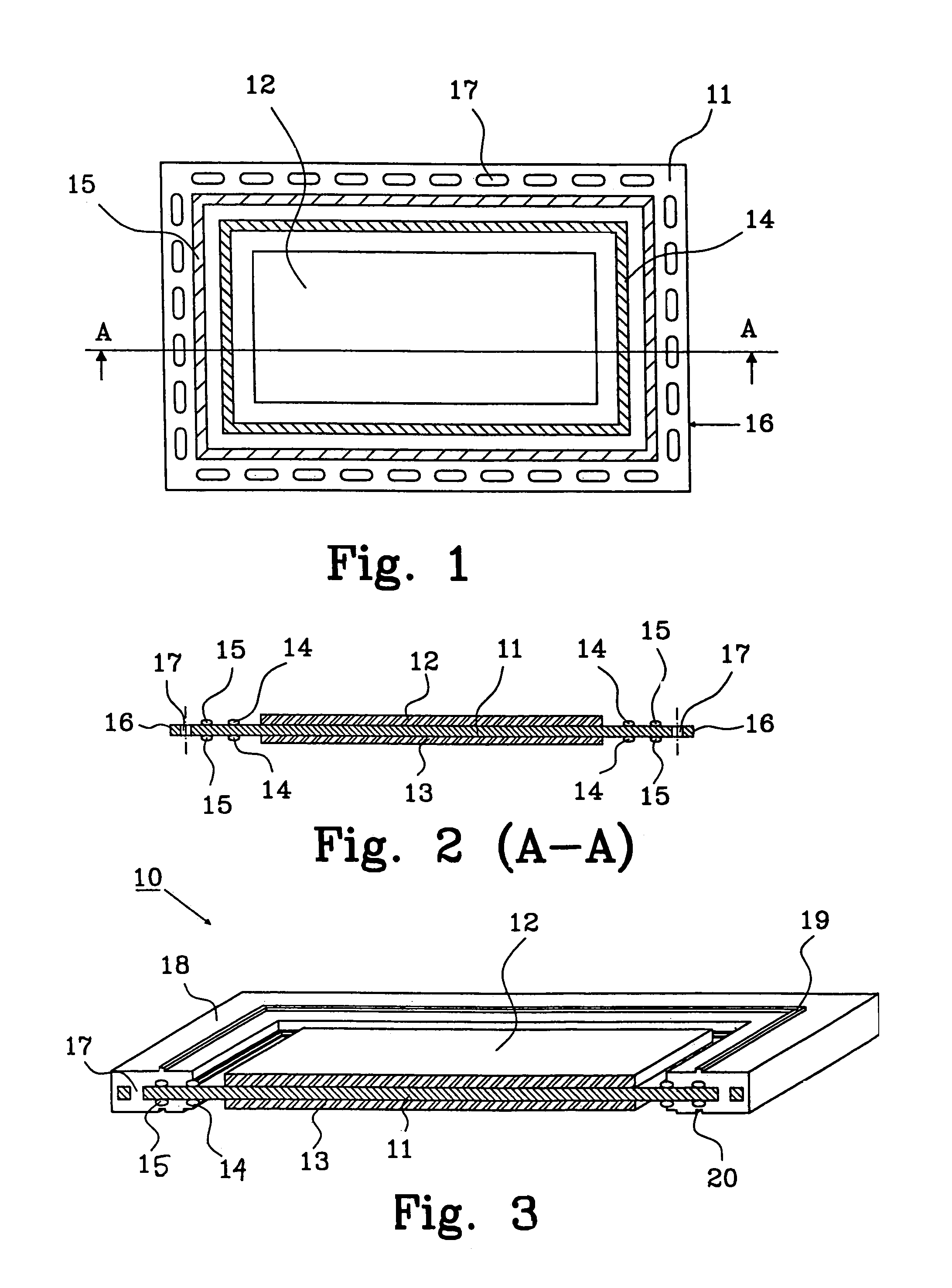
[0043]FIG. 1 is a planar view and FIG. 2 is a cross sectional view (along A—A in FIG. 1) of a biplate assembly. Normally a biplate assembly requires a frame to make up the individual cells within the battery, but for the sake of clarity the frame is omitted in FIGS. 1 and 2.

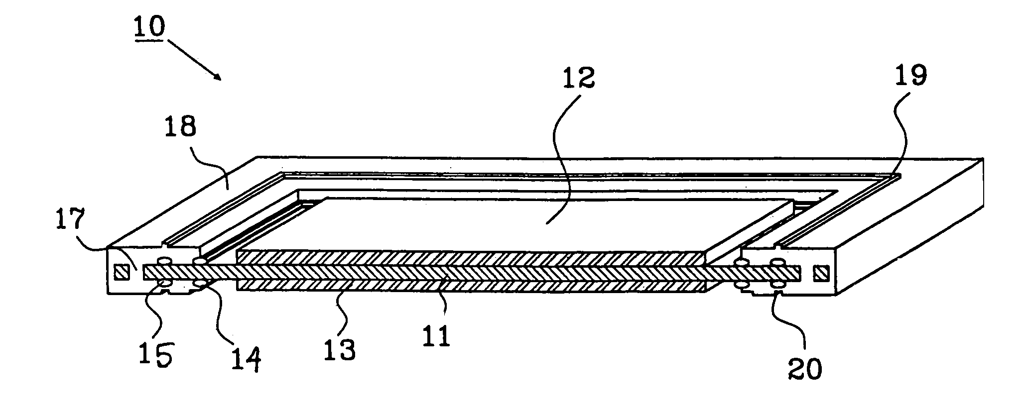
[0044]The biplate assembly comprises a biplate 11, preferably made from Nickel or Nickel plated steel. A positive electrode 12 and a negative electrode 13 are attached to each side, respectively, of the biplate 11. Each electrode is arranged to cover only a central portion of the side of the biplate 11 to leave space for implementing the sealing and heat conducting means. A hydrophobic barrier 14, which prevents formation of an electrolyte path between cells, is provided on both sides of the biplate between the electrode and an elastomer 15. The elastomer 15 prevents gas leakage from the cell together with the frame (not shown). The elastomer is provided between the barrier 14 and the edge 16 on both sides of the...

second embodiment

[0055]FIG. 4 is a planar view and FIG. 5 is a cross sectional view (along A—A in FIG. 4) of a biplate assembly, where the frame is omitted for the sake of clarity.

[0056]The biplate assembly comprises a biplate 21, preferably made from Nickel or Nickel plated steel. A positive electrode 12 and a negative electrode 13 are attached to each side, respectively, of the biplate 21. Each electrode is arranged to cover only a central portion of the side of the biplate 21 as described in connection with FIGS. 1 and 2. An electrolyte barrier 22 is provided on both sides of the biplate between the electrode and an elastomer 23, which is provided between the electrolyte barrier 14 and the edge 16 on both sides of the biplate 21.

[0057]In this embodiment no holes are provided around the perimeter of the biplate 21. The ring of elastomer 23 is in this embodiment made wider, thereby achieving an even better seal to prevent gas leakage due to the elastic properties of the elastomer 23, as will come m...

third embodiment

[0060]FIG. 7 shows a cross-sectional view of a part of a complete biplate assembly 40, including a frame 41. The frame encompass only the ring of elastomer 23 on both sides of the biplate 21. The frame 41 also has guiding means 19, 20 as described above, with tapered surfaces 42 and 43 provided on each side of the tongue 19. The advantage with this arrangement is the same as described in connection with FIG. 6.

[0061]It is essential that the frame encompass the ring of elastomer to prevent gas leakage from one cell to another. The electrolyte barrier, preventing electrolyte leakage, will function the same irrespectively if the frame partly encompass it or not.

[0062]FIGS. 8a–8f illustrates a manufacturing process in cross section for a bipolar battery according to the invention.

[0063]A biplate 21 is provided in FIG. 8a, which has a predetermined size. The size may vary depending on the intended application.

[0064]FIG. 8b illustrates the appearance after the steps of providing an electr...


PUM

PropertyMeasurementUnit
Hydrophobicityaaaaaaaaaa

Abstract

The present invention relates to a bipolar battery having at least two battery cells comprising: a sealed housing, a negative end terminal, a positive end terminal, at least one biplate assembly arranged in a sandwich structure between said negative and positive end terminals, and a separator, including an electrolyte, arranged between each negative and positive electrode forming a battery cell. The biplate assembly is provided with an inner barrier of a hydrophobic material around the negative and the positive electrode, respectively, and an outer seal around the edge of each biplate. Each end terminal is provided with a terminal seal. The edge of each biplate is positioned close to the sealed housing to provide means to conduct heat from each biplate assembly to the ambient environment. The invention also relates to a method for manufacturing a bipolar battery and a biplate assembly.

Description

TECHNICAL FIELD[0001]The present invention relates to a bipolar battery. The invention also relates to a method for manufacturing a bipolar battery and a biplate assembly.BACKGROUND OF THE INVENTION[0002]In theory, bipolar batteries can be used to improve battery energy storage capacity on a weight and volume basis, to reduce packing weight and volume, to provide stable battery performance and low internal resistance.[0003]A bipolar battery construction comprises an electrically conductive bipolar layer, so called biplate, that serves as electrical interconnection between adjacent cells in the battery as well as a partition between the cells. In order for the bipolar construction to be successfully utilised, the biplate must be sufficiently conductive to transmit current from cell to cell, chemically stable in the cell's environment, capable of making and maintaining good contact to the electrodes and capable of being electrically insulated and sealable around the boundaries of the ...

Claims


Application Information

Patent Timeline
IPC IPC(8): H01M6/48H01M10/18H01M2/08H01M4/02H01M10/02H01M10/04H01M10/28H01M10/30H01M10/34H01M10/50
CPCH01M10/0413H01M10/0418H01M10/0468H01M10/0486H01M10/5032H01M10/5042H01M10/5051H01M10/5004H01M10/30H01M10/345Y10T29/4911H01M10/5016H01M2004/029Y10T29/49108H01M10/625H01M10/6553H01M10/647H01M10/654H01M10/613Y02E60/10Y02P70/50
Inventor FREDRIKSSON, LARSPUESTER, NEIL
Owner NILAR INT AB
Learn More