
Spread spectrum transmitter and spread spectrum receiver

a technology of spread spectrum and receiver, which is applied in the field of improvement of spread spectrum transmitter and receiver of spread spectrum radio communication system, can solve the problems of running out of employable pn codes and increase in the scale of associated transmitter and receiver circuitry, so as to achieve the effect of minimizing the scale of circuitry of transmitter and receiver of the conventional m-ary/ss system and increasing the transmission ra

Inactive Publication Date: 2006-08-22
MITSUBISHI ELECTRIC CORP
View PDF9 Cites 108 Cited by
  • Summary
  • Abstract
  • Description
  • Claims
  • Application Information

AI Technical Summary

Benefits of technology

The invention provides a spread spectrum transmitter and receiver capable of transmitting and receiving information at a higher rate than conventional systems, while minimizing the increase in circuitry size. The transmitter converts information into parallel data sequences, which are then distributed to multiple channels. The receiver calculates partial correlation values between the transmission signal and a set of partial spreading codes, and identifies the highest correlation value as the most likely demodulation sequence. The receiver also corrects delay differences in the demodulated data sequences. The invention allows for faster and more efficient communication with higher transmission rates.

Problems solved by technology

However, this results in an increase in scale of circuitry of associated transmitter and receiver.
For a limitation to the number of PN codes concurrently employable within an entire spread spectrum communications system, the allotment of a plurality of PN codes to a single transmitter results in running out of employable PN codes.

Method used


Image

  • Spread spectrum transmitter and spread spectrum receiver
  • Spread spectrum transmitter and spread spectrum receiver
  • Spread spectrum transmitter and spread spectrum receiver

Examples


first embodiment

[0037]this invention will be explained below.

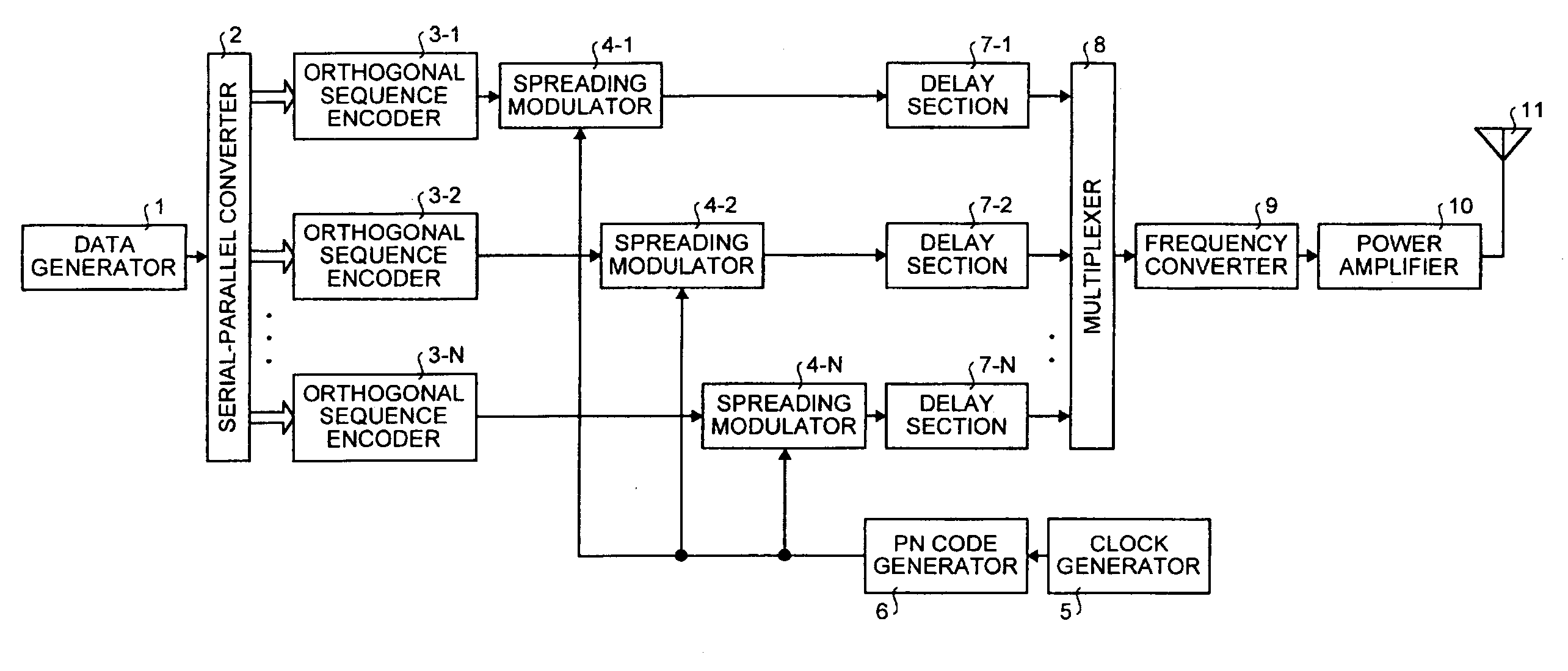
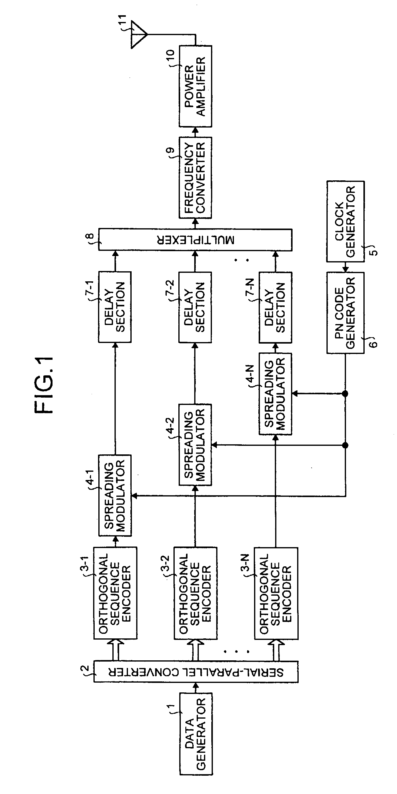
[0038]FIG. 1 is a block diagram of the spread spectrum transmitter in the first embodiment. As shown in FIG. 1, the spread spectrum transmitter is provided with a data generator 1 that generates an information signal, a serial-parallel converter 2 that converts the information signal into N prescribed parallel data sequences, orthogonal sequence encoders 3-1 to 3-N that convert N parallel data sequences into prescribed N orthogonal code sequences, respectively, and spreading modulators 4-1 to 4-N that perform spreading processes on the N orthogonal code sequences to generate SS signals, a clock generator 5. The spread spectrum transmitter is also provided with a PN code generator 6 that generates a prescribed PN code, N delay sections 7-1 to 7-N that provides prescribed delays to the SS signals, respectively, a multiplexer 8 that multiplexes the SS signals provided with the delays to generate a multiplex SS signal, a frequency converter 9...


PUM


Abstract

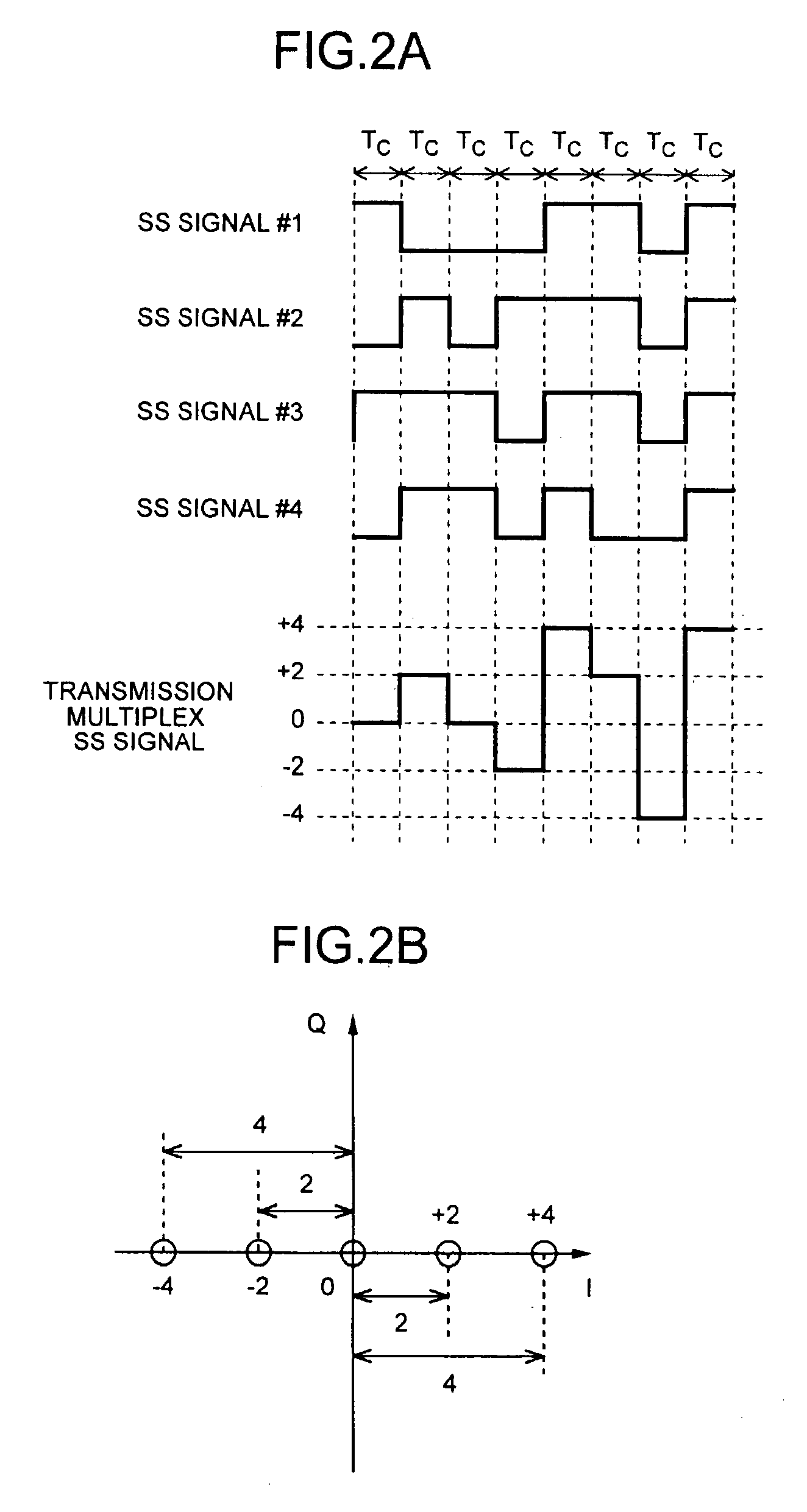
A spread spectrum transmitter provides delays having different magnitudes to spread spectrum (SS) signals for a plurality of channels, and multiplexes the SS signals to generate transmission multiplex SS signal. A spread spectrum receiver calculates a partial correlation value between the transmission multiplex SS signal and spreading codes multiplied to the SS signals, multiplies the partial correlation values by a prescribed matrix prepared based on each orthogonal code sequence to calculate a plurality of orthogonal correlation values. The receiver identifies for a respective channel each parallel data sequence related in advance to an orthogonal code sequence whose orthogonal correlation value is a maximum, corrects delay differences of the parallel data sequences, and then performs sampling and parallel-serial conversion to obtain a serial demodulated data sequence.

Description

BACKGROUND OF THE INVENTION[0001]1) Field of the Invention[0002]The present invention relates to an improvement to a transmitter and a receiver of a spread spectrum radio communications system. More particularly, this invention relates to an increased transmission rate of a spread spectrum transmitter and a spread spectrum receiver employing an M-ary / SS system.[0003]2) Description of the Related Art[0004]In recent years, attention has been focused on spread spectrum (hereinafter referred to as “SS”) systems as a transmission system of information signals such as image signals and audio signals, in the field of mobile communications system.[0005]Among such SS systems, an “M-ary / SS system” is adaptive for increasing the transmission rate and has been used widely. In the M-ary / SS system, mutually orthogonal 2K code sequences (hereinafter referred to as “orthogonal code sequences”) are stored in advance in both a transmitter and a receiver. The transmitter sequentially generates data se...

Claims


Application Information

Patent Timeline
Patent Type & Authority Patents(United States)
IPC IPC(8): H04B1/707H04J11/00H04J13/00H04J13/18H04L7/00
CPCH04J13/0022H04B1/70752
Inventor OKUBO, SEIJIUCHIKI, TATSUYAKOJIMA, TOSHIHARU
Owner MITSUBISHI ELECTRIC CORP
Learn More