
Synthetic equivalence test circuit for circuit breaker testing

a test circuit and circuit breaker technology, applied in the direction of circuit interrupter testing, measurement devices, instruments, etc., can solve the problems of increasing the source voltage in the high-current circuit, the characteristics of the primary current do not conform to the conditions, and the object is unjustified, so as to reduce the high current, shorten the arcing time, and reduce the arc voltage

Inactive Publication Date: 2006-08-22
SLAMECKA ERNST
View PDF4 Cites 1 Cited by
  • Summary
  • Abstract
  • Description
  • Claims
  • Application Information

AI Technical Summary

Benefits of technology

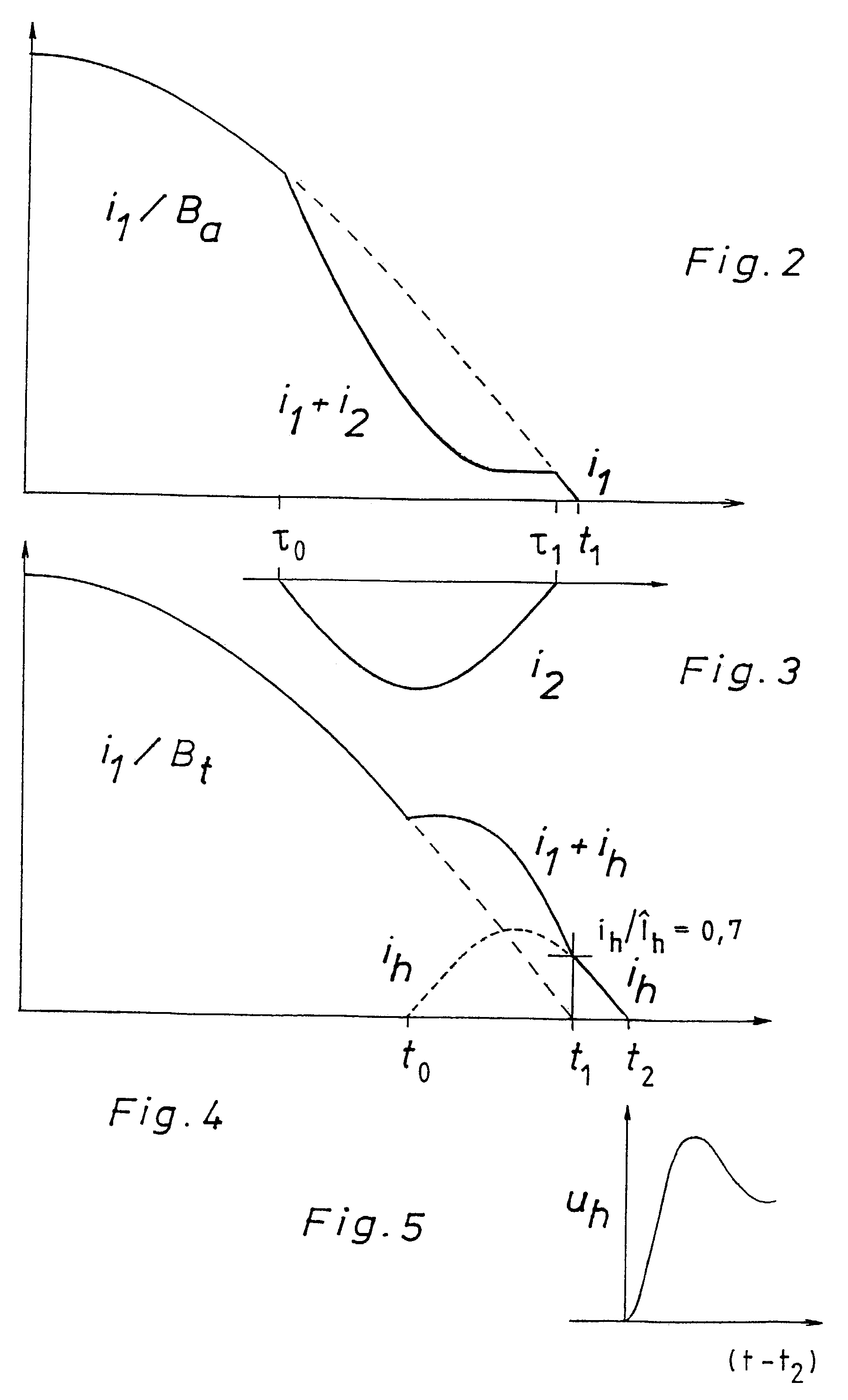
[0017]3) A counter-current in an autonomous LC or RC current circuit connected parallel to the auxiliary switch reduces the high current in the auxiliary switch; this makes an auxiliary switch with substantially diminished arc voltage possible, e.g., represented by a vacuum switch, and the current distortion remains within permissible limits without the use of a high-current transformer; also a shortening of the arcing time by a relatively delayed contact separation can relieve the auxiliary switch, and especially effective is the combination of both measures.

Problems solved by technology

However, a more accurate analysis of the German patent specification 962 731 by Fritz Weil (“Weil '731”) describing a synthetic test circuit, and of German patent specification 975 303 by G. Dobke (“Dobke '303”), proves that the association of these names with the circuit was an oversight and, therefore, objectively unjustified.
In Weil '731, it is said of the state of the art: “A known test arrangement of this type (“artificial circuit”) has the disadvantage that the characteristics of the primary current do not conform to the conditions of the natural test shortly before its zero crossing and the inception of high voltage as recovery voltage, respectively.
The known remedy, a high-current transformer, to increase the source voltage in the high-current circuit, is costly and reduces its current yield.

Method used


Image

  • Synthetic equivalence test circuit for circuit breaker testing
  • Synthetic equivalence test circuit for circuit breaker testing
  • Synthetic equivalence test circuit for circuit breaker testing

Examples


Embodiment Construction

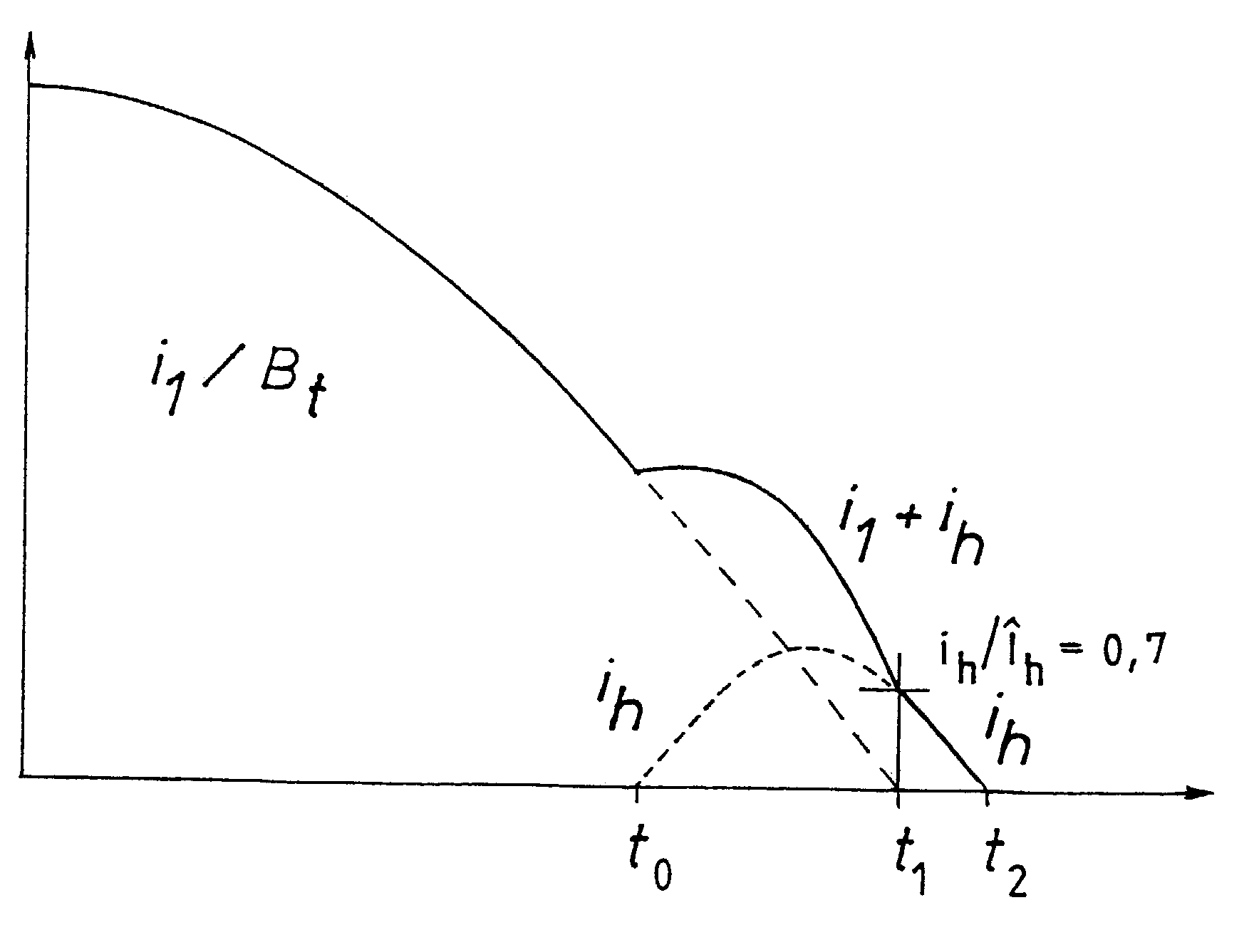
[0032]The high-current circuit of FIG. 1 comprises: a generator G as a high-current source, with or without a following transformer, if applicable; a resulting inductance L1 co-representing an additional current-limiting inductance; a master circuit breaker (not shown); a making switch (not shown); an auxiliary switch Ba; and a test switch Bt.

[0033]Also shown in FIG. 1, the high-voltage oscillating circuit comprises: a capacitance Ch chargeable to high voltage; an inductance Lh; a triggerable spark gap SGh; a capacitance Ct parallel to the test switch, if necessary; an ohmic resistance connected in series; an ohmic resistance Rt connected parallel to the test switch; and, if necessary, a line impedance simulating circuit LSC between the test switch and capacitance Ct.

[0034]The control consists of a high-current transformer CTh and a device for generating a time-programmable ignition impulse for the triggerable spark gap CDh.

[0035]With the master circuit breaker and the making switch...


PUM


Abstract

A method for testing high-voltage alternating-current power switches in a synthetic test circuit has the step of connecting a high-voltage oscillating circuit in parallel to a test switch Bt in a time interval before the current zero of an interruptible high current, which is determined by a half-cycle duration (Th / 2) of the oscillating current (ih) less the duration of equivalence (Δtse) of the sole flow of the oscillating current as sequential current in the test switch with a stress exerted upon the switch by the homogeneous current in a direct test circuit. The sequential-current flow duration of the equivalence results, at least approximately, from the comparison of the values of common physical stress parameters acting in the test switch during the test, on the one hand, in the synthetic test circuit and, on the other hand, in the direct test circuit.

Description

[0001]The present invention relates to breaking-capacity test circuits with the main characteristics indicated in the characterizing clause of patent claim 1. The content of my co-pending patent application, U.S. Ser. No. 10 / 147,552, filed 16 Jul. 2002, is incorporated by reference as if fully recited herein.BACKGROUND OF THE ART[0002]Synthetic test circuits are known from IEC publication 60427, third edition 2000-04, page 95, Figure BB1.[0003]The “typical current injection circuit with voltage circuit in parallel with the test circuit-breaker” was developed in the early 1950s at the initiative of Professor J. Biermanns, who was then director of the new High-Voltage Institute of AEG in Kassel-Bettenhausen and was formerly director of the AEG-Transformatoren-Fabrik Oberschöneweide (“TRO”) in Berlin, to increase the direct testing capacity of the testing department of the Institute.[0004]During the development work, this synthetic test circuit was known in the Institute as “artificial...

Claims


Application Information

Patent Timeline
Patent Type & Authority Patents(United States)
IPC IPC(8): G01R31/02G01R31/333
CPCG01R31/3336
Inventor SLAMECKA, ERNST
Owner SLAMECKA ERNST
Learn More