
Multi-phase flow pumping means and related methods

a multi-phase fluid and pumping means technology, applied in the direction of wind motors with parallel air flow, liquid fuel engines, motors, etc., can solve the problems of fluids that can create problems, unwanted problems in the pumping process, and the success of centrifugal pumps in pumping multi-phase fluids is limited, and the success rate of multi-phase fluids is known

Inactive Publication Date: 2006-08-22
UNITEC INST OF TECH +1
View PDF28 Cites 26 Cited by
  • Summary
  • Abstract
  • Description
  • Claims
  • Application Information

AI Technical Summary

Benefits of technology

[0022]Preferably said at least one nozzle provides, an increase in velocity head to said bled flow prior to the point of injection by reducing the flow area of the fluid connection means.

Problems solved by technology

In certain situations the entrained gas within a liquid medium will cause unwanted problems in the pumping process.
The handling of such fluids can create problems.
The problems are strictly multi-phase, which essentially means that as the gas or steam content increases the pressure head degrades multi-phase pumps which have relatively good performance characteristics are normally of screw type.
While centrifugal pumps are known to be used in the pumping of multi-phase fluids they have had limited success.
The present conventional designs of centrifugal pumps are not adequate due to their inability to pump high gas volume fraction media.
The composition of the fluid flow and variety of flow configurations where each phase has a different velocity in such cases makes the flow difficult to define.
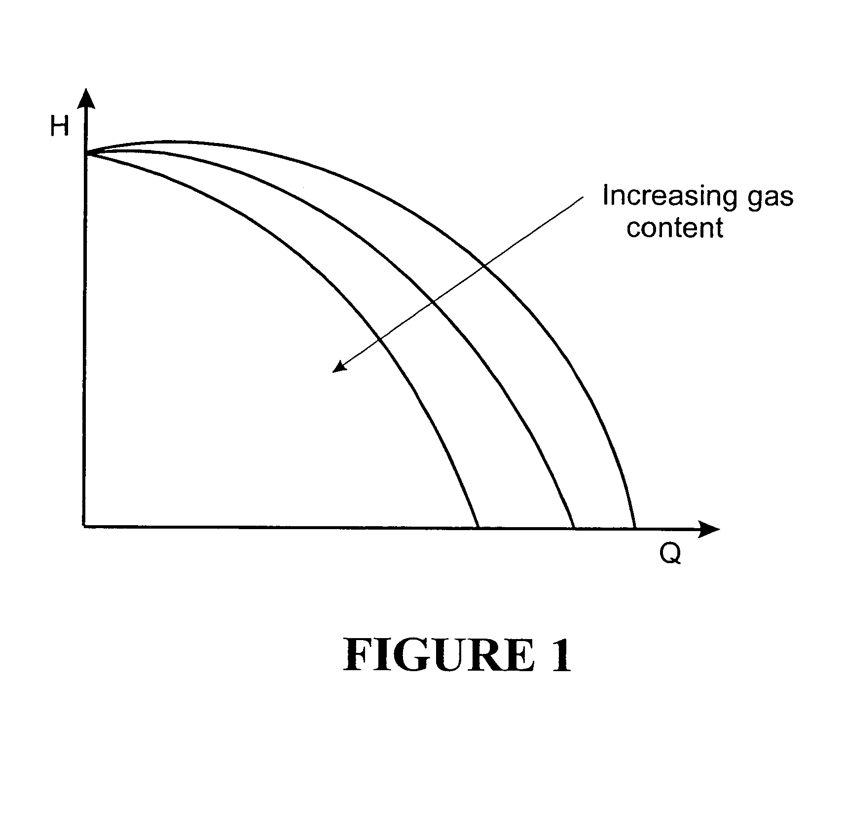
It is known that where free gas is present in a liquid being pumped the head, power and efficiency of rotodynamic pumps are known to decrease.
Although multi-phase products have been pumped for many years with double screw type pumps, centrifugal impeller pumps have shown serious departures from published performance curves.
The decrease in efficiency of pumping multi-phase flow suggests that some additional loss mechanisms arise when gassy liquids are pumped.
1) gas locking or “choking”, and
2) instability in the head-capacity curve which causes surge.
It is not surprising that a blade design for incompressible single-phase flow is not very effective in multi-phase flow and produces choking for relatively high gas volume fraction.

Method used


Image

  • Multi-phase flow pumping means and related methods
  • Multi-phase flow pumping means and related methods
  • Multi-phase flow pumping means and related methods

Examples


example

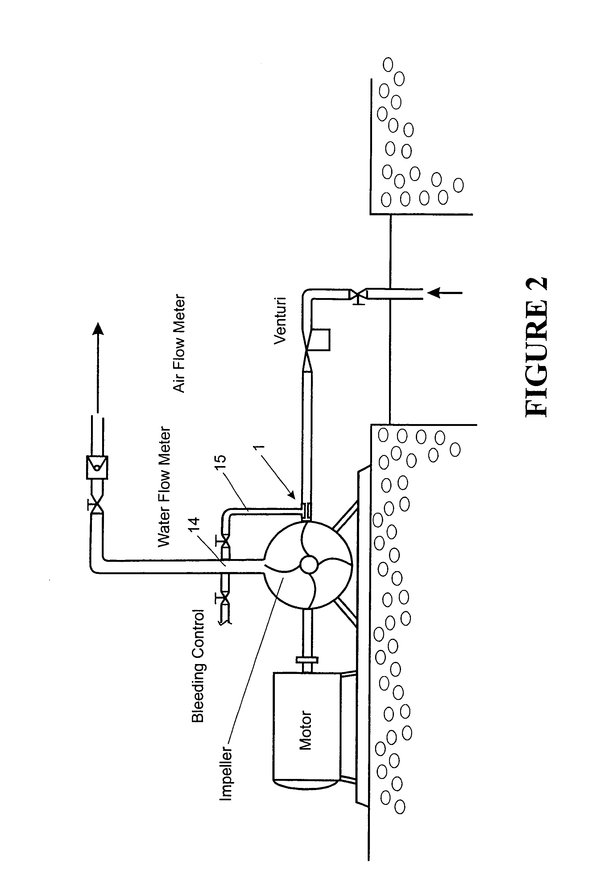
[0063]The following is a description of details of experiments conducted on a centrifugal pump. The pump was tested in two modes, a first, normalising mode where the fluid being pumped was 100% water and a second mode at various degrees of air void fraction. This was repeated for two different impeller configurations, a first 4 blade impeller and a second 3 blade impeller.

The Setup

[0064]The centrifugal pump used was operating with low head of 2 meters. The specifications of the pump are as follows

[0065]

ItemPump size190 × 160 × 100 mmPump typeVerticalCentrifugalSingle suctionSingle dischargeNozzle units4 × 12 mm dBNumber of blades3 and 4Impeller diameter50 mmInlet blade angle (degrees)79 / 72 degreesOutlet blade angle (degrees)42 / 47 degreesRated head2 m (6.56 ft)Rated flow0.8 l / s (12.7 gpm)Specific speed (dimensionless)2,431Suction specific speed (dimensionless)6,874Motor power (kW)0.25Motor (rpm)2,800

[0066]The test pump has modified centrifugal impellers (3 vanes and 4 vanes) and a si...


PUM


Abstract

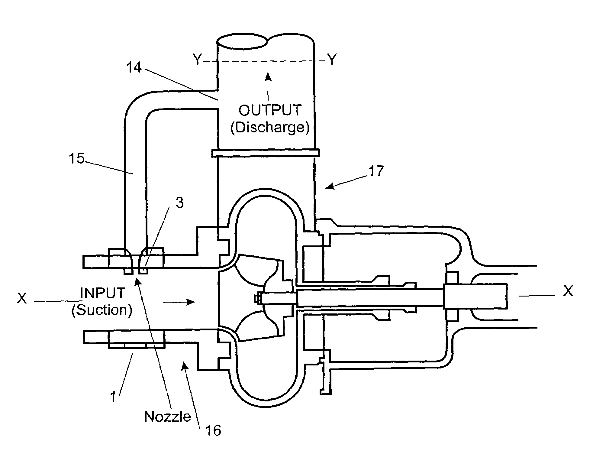
A method of pumping and related arrangement for multi-phase fluid flow wherein a centrifugal pump is used for the suction and delivery of the multi-phase fluid which has a fluid communication providing portion to provide a communication of fluid bled from the outlet at a higher pressure to be injected into the inlet conduit of the centrifugal pump in operation. The centrifugal pump is provided with an impeller which has a plurality of vanes configured to define there between larger passageways when compared to a conventional centrifugal pump which would operate in or near optimum conditions when pumping liquid only.

Description

[0001]This is a nationalization of PCT / NZ00 / 00134, filed Jul. 21, 2000 and published in English.[0002]The present invention relates to improvements in or relating to multi-phase flow pumping means and related methods.BACKGROUND ART[0003]Two-phase fluid pumping covers a large spectrum of pump operation and applications. In certain situations the entrained gas within a liquid medium will cause unwanted problems in the pumping process. For the off-shore oil industry there is now considerable interest in pumping liquids with a high gas content, similar as there has been for some time in the pumping systems supplying aircraft gas turbines. This interest is also found within the geothermal industry. In many oil fields, the wells contain mixtures of gas and oil in varying proportions. The handling of such fluids can create problems. The problems are strictly multi-phase, which essentially means that as the gas or steam content increases the pressure head degrades multi-phase pumps which ha...

Claims


Application Information

Patent Timeline
IPC IPC(8): F04D27/00F04D31/00F04D29/22F04D29/44
CPCF04D31/00F04D29/2222
Inventor ZAHER, MOUAFAK ARIF
Owner UNITEC INST OF TECH
Learn More