
Ball valve with shear bushing and integral bracket for stem blowout protection

a technology of ball valve and stem, applied in the field of ball valve, can solve the problems of valves being blown out, valves are often subjected to extremely high pressure and temperature, valves suffer, etc., and achieve the effect of preventing the blowout of the stem

Active Publication Date: 2006-08-22
MOGAS IND
View PDF18 Cites 38 Cited by
  • Summary
  • Abstract
  • Description
  • Claims
  • Application Information

AI Technical Summary

Benefits of technology

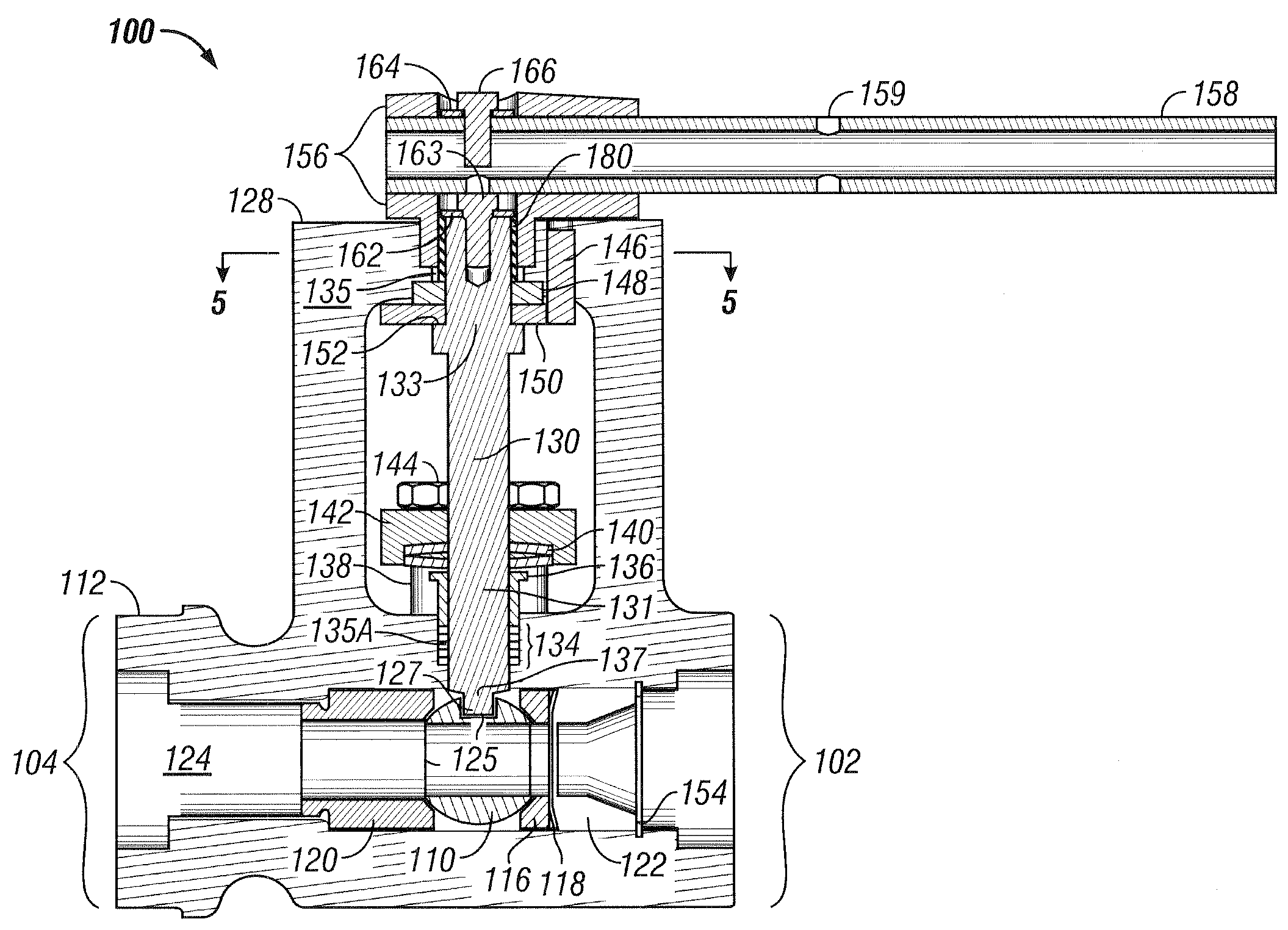
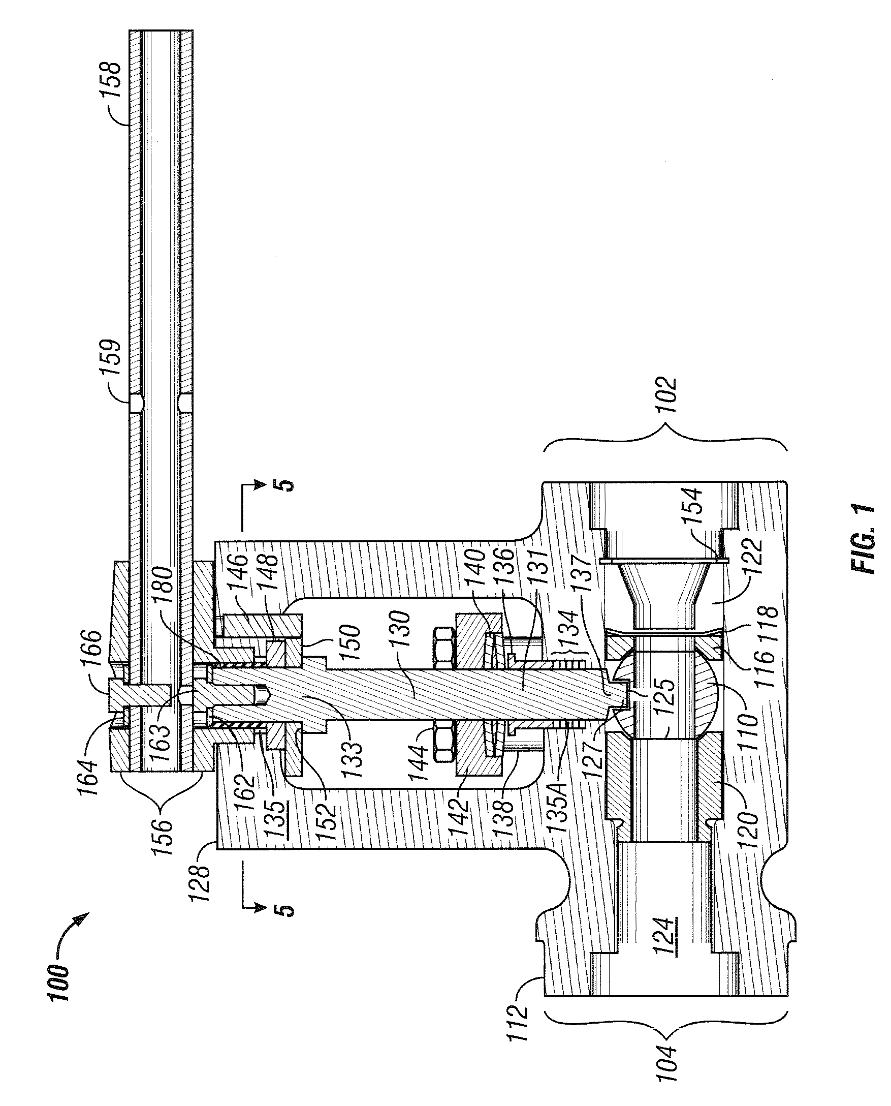
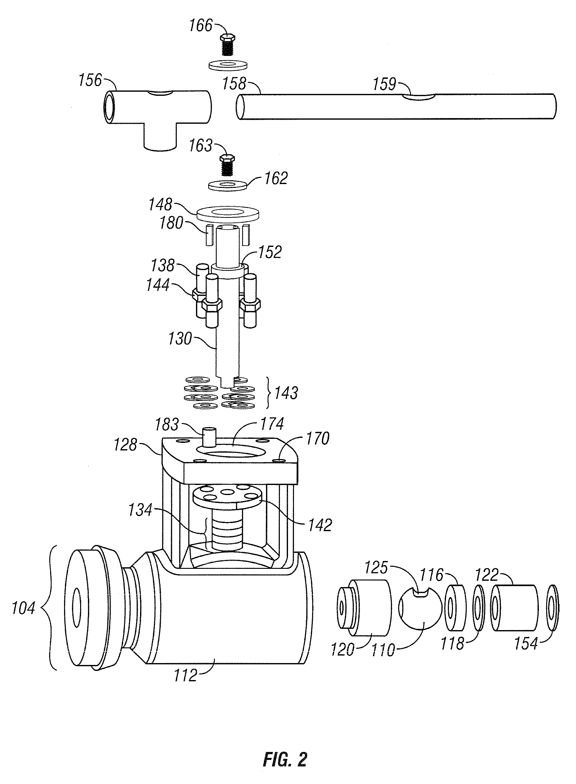
[0010]The present invention is directed to a high pressure ball valve wherein the body has an integral bracket cooperatively coupled to the valve stem to prevent blowout of the stem under high pressure conditions. The stem includes a shoulder which engages a contiguous shear bushing having an outer diameter greater than that of the stem bore, thereby preventing removal of the stem from the valve body.

Problems solved by technology

Conventional ball valves are often subjected to extremely high pressures and temperatures in the various processes where they are used.
Many prior art valves suffer in that they leak past seals associated with the rotatable closure members.
The tendency for valves to leak increases under conditions of high pressure and high temperature, and is especially common in severe service valves which operate through a wide range of temperatures.
However, the prior art bonnet designs suffer from shortcomings in their design.
The split gland and split bushing increase the number of critical parts for possible failure and increase the time necessary to install the stem as efforts must be made to ensure proper alignment of the stem within the stem passage.
Misalignment of the stem in the stem passage of the bonnet can result in improper bearing of the axial load leading to leakage of the stem seals and unseating of the ball with the upstream and downstream seats.
Furthermore, use of the split gland can result in an unbalanced compression of the packing rings, also leading to leakage in the valve.
The use of split-bushings requires the use of an additional bearing surface because the split bushing does not provide an adequate planar surface against which parts can freely move, instead requiring a thrust bearing located below the split bushing, and a stem bushing located above the split bushing.
This creates a risk that axial movement of the handle can be translated through the stem to the ball, unseating the ball from the upstream and downstream inserts, and possibly damaging the seats.

Method used


Image

  • Ball valve with shear bushing and integral bracket for stem blowout protection
  • Ball valve with shear bushing and integral bracket for stem blowout protection
  • Ball valve with shear bushing and integral bracket for stem blowout protection

Examples


Embodiment Construction

[0022]Detailed embodiments of the present invention are disclosed herein. However, it is understood that the disclosed embodiments are merely exemplary of the invention, which may be embodied in various forms. Specific structural and functional details disclosed herein are not intended to be limiting, but merely illustrations that can be modified within the scope of the attached claims.

[0023]The present invention is directed to a ball valve for the passage of fluid under high pressure wherein the body of the valve has a bracket produced integral to the main body of the valve. The integral bracket helps to prevent leakage in the stem passage and, when subjected to high pressure conditions, blowout of the valve stem. Blowout is prevented through the use of a contiguous shear bushing which has an outer diameter greater than the inner diameter of the stem passage through the bracket. The manufacture of a product with integrated components can, as is well known, reduce production costs. ...


PUM


Abstract

A valve 100 comprising a one piece valve body 112 having an axial fluid bore 124 and a rotatable fluid control element 110. The body 112 includes an integral bracket 128 which provides an open access area between the bracket 128 and the main body 112 of the valve 100. A valve stem 130 is disposed within a stem bore 135, and 137 extending from the valve body 112 to the bracket 128, and engaging the flow control element 110. A contiguous single piece gland flange 142 secures packing 134 disposed between a valve body bore 137 and the stem 130. The stem 130 includes an enlarged shoulder 152 which engages a contiguous single piece shear bushing 148 having a diameter greater than the diameter of the stem bore 130, thereby preventing removal and / or blowout of the stem 130 without prior removal of the shear bushing 148.

Description

BACKGROUND OF INVENTION[0001]This invention relates to a ball valve for the passage of fluids wherein the valve includes an integral bracket providing protection against blowout of the stem when subjected to high pressure and high temperature conditions, and more particularly to a ball valve with an integral bracket and a contiguous blowout prevention bushing.[0002]Conventional ball valves are often subjected to extremely high pressures and temperatures in the various processes where they are used. Many prior art valves suffer in that they leak past seals associated with the rotatable closure members. The tendency for valves to leak increases under conditions of high pressure and high temperature, and is especially common in severe service valves which operate through a wide range of temperatures.[0003]Ball valves operating under high pressure conditions often include a bonnet attached to the body of the valve to prevent blowout of the stem. The bonnet can be integral to the valve b...

Claims


Application Information

Patent Timeline
IPC IPC(8): F16K5/06
CPCF16K5/0642F16K5/0647F16K31/602F16K27/067F16K5/0657
Inventor HALL, BRIAN R.WILLIAMS, JR., JOHN B.
Owner MOGAS IND
Learn More