
Device for production of hydrogen from effluents of internal combustion engines

a technology of internal combustion engine and exhaust gas, which is applied in the direction of combustion air/fuel air treatment, machines/engines, mechanical equipment, etc., can solve the problems of harmful pollutants and no attempt to generate hydrogen from the exhaust gas of an internal combustion engine, and achieve the effect of reducing the emission of pollutants

Inactive Publication Date: 2006-08-15
COUNCIL OF SCI & IND RES
View PDF8 Cites 48 Cited by
  • Summary
  • Abstract
  • Description
  • Claims
  • Application Information

AI Technical Summary

Benefits of technology

The present invention provides a device and method for producing hydrogen from the exhaust of an internal combustion engine. The device includes a steam generator and a reformer connected to the engine, with the reformer containing a hydrogen separation membrane. The device can be placed close to the engine to use heat generated by the engine for the production of steam. The hydrogen separation membrane can separate pure hydrogen from the exhaust gas. The device can also include slots containing different catalysts to decompose hydrocarbons and obtain hydrogen rich gases. The hydrogen rich gases can be used as fuel for the engine or can be further purified and used to reduce emissions. The method involves mixing steam with exhaust gas from the engine in the reformer, which contains slots containing different catalysts to obtain hydrogen rich gases and pure hydrogen. The pure hydrogen can then be used as fuel or to reduce emissions in the combustion process.

Problems solved by technology

Burning of these fuels in internal combustion engines produces energy depending on efficiency of the engine, and a large quantity of un-burnt / partially burned fuel and other pollutants.
Some of these pollutants are harmful and some are harmless.
However, no attempt has been made to generate hydrogen from the exhaust gas of an internal combustion engine.
The drawbacks are the method is useful for the reduction of pollutants emission but it does not make use of large quantity of hydrocarbons the engine emits and moreover it does not stop emission of all the pollutants.
The drawbacks are the method uses valuable chemicals (fuels) that have many use and does not use the waste hydrocarbons generated in the internal combustion engine.
The drawbacks are it uses the raw methane gas for hydrogen production and does not use the waste hydrocarbons generated in the internal combustion engine.
The drawbacks are it uses raw methanol for hydrogen production and does not use waste hydrocarbons generated in the internal combustion engine.
The drawbacks are it requires fuel and it does not make use of waste hydrocarbon generated by the internal combustion engine.

Method used


Image

  • Device for production of hydrogen from effluents of internal combustion engines
  • Device for production of hydrogen from effluents of internal combustion engines

Examples


Embodiment Construction

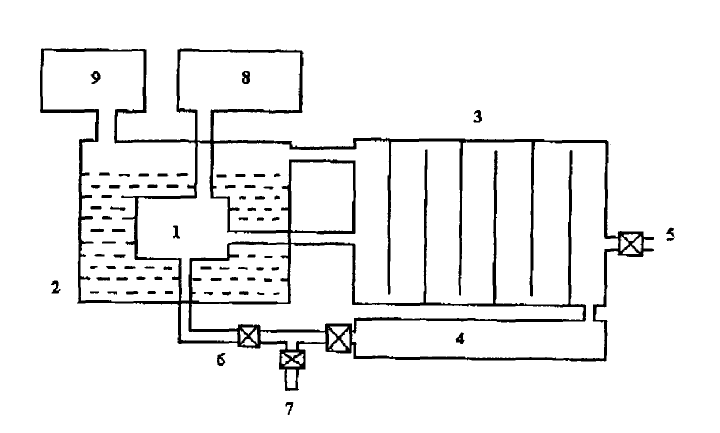
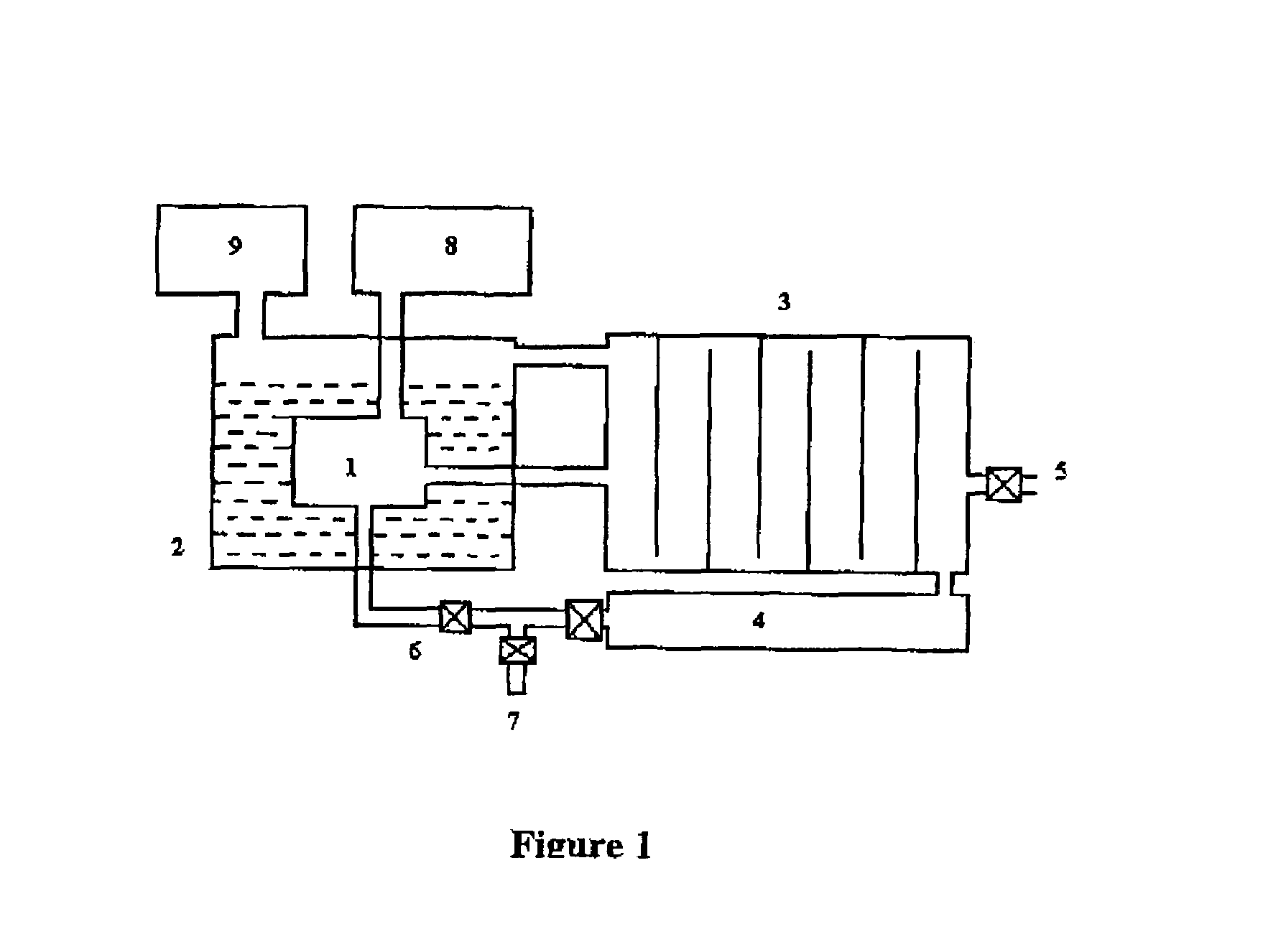
[0028]The present invention provides a device for production of hydrogen from effluents of internal combustion engine. The device is described with reference to the figure accompanying this specification. The internal combustion engine (1) has a steam generator (2) built around and in close thermal contact therewith. The exhaust of the internal combustion engine (1) and steam generator (2) are connected to a reformer (3) provided with a plurality of slots, different catalysts being provided in each slot. The reformer (3) is provided with a first outlet and a second outlet. The first outlet is connected to a hydrogen separation membrane (4) and the second outlet (5) emits hydrogen rich fuel. The hydrogen separation membrane (4) is provided with a first outlet and a second outlet. The first outlet (6) is connected can be connected to the same or another internal combustion engine (1) and the second outlet (7) emits pure hydrogen which can be used for fuel cells.

[0029]The steam generat...


PUM


Abstract

The present invention discloses a device for production of hydrogen from effluents of internal combustion engine, which comprises a steam generator, which derives thermal energy from the internal combustion engine and generates steam, the steam and the exhaust of the internal combustion engine being mixed in a reformer reactor and hydrogen gas being extracted through hydrogen separation membrane.

Description

FIELD OF THE INVENTION[0001]The present invention relates to a device for production of hydrogen from effluents of internal combustion engines. More particularly the present invention relates to generation of hydrogen for fuel cells and hydrogen based internal combustion engines by using unburnt / partially burned fuel and other organic compounds emitted from the exhaust of an internal combustion engine.BACKGROUND OF THE INVENTION[0002]Internal combustion engines burn fossil fuels such as petrol, diesel, kerosene, natural gas etc., and generate energy, which is used for transportation, pumping of liquids and for generating electricity. Fossil fuels are basically hydrocarbons, which contain predominantly carbon and hydrogen atoms. Burning of these fuels in internal combustion engines produces energy depending on efficiency of the engine, and a large quantity of un-burnt / partially burned fuel and other pollutants. 70% of air pollution in urban areas is due to burning of fossil fuels in ...

Claims


Application Information

Patent Timeline
Patent Type & Authority Patents(United States)
IPC IPC(8): F02B75/12
CPCC01B3/382F02B43/10F02G5/02F02M25/10F02M25/12C01B3/501Y02T10/32C01B2203/0233C01B2203/0244C01B2203/0261C01B2203/0277C01B2203/0283C01B2203/0405C01B2203/0465C01B2203/0475C01B2203/0485F01N2240/30F02M27/02Y02T10/121Y02T10/166Y02T10/12Y02T10/30
Inventor MIRJI, SANMATI A.
Owner COUNCIL OF SCI & IND RES
Learn More