
Method of making a jacketed preform for optical fibers using OVD

a technology of optical fibers and preforms, applied in the direction of cladding optical fibers, manufacturing tools, instruments, etc., can solve the problems of increasing the difficulty of collapsing with thick-walled or large substrate tubes, and the refractive index profile is substantially more complex, so as to facilitate the manufacture of step-wise refraction index profiles. , the effect of being particularly economical and effective production

Inactive Publication Date: 2006-08-15
HERAEUS TENEVO
View PDF32 Cites 55 Cited by
  • Summary
  • Abstract
  • Description
  • Claims
  • Application Information

AI Technical Summary

Benefits of technology

[0010]Therefore the object of the invention is to provide an effective and economical process for the production of a preform whereby complex refractive index profiles may be produced in a highly productive manner, and to provide a substrate tube suitable therefor, in which substrate tube less core glass material is needed, either for the internal deposition process or for the core glass rod in the rod-in-tube process.

Problems solved by technology

However, in the course of optimization of optical fibers, in particular for the simultaneous transmission of several wavelengths and for higher transmission rates, fiber designs are being developed which have substantially more complex refractive index profiles.
But this is limited due to the softening and the plastic deformation of the substrate tube.
Moreover, the collapsing becomes increasingly difficult with thick-walled or large substrate tubes and with thick inner layers.

Method used


Image

  • Method of making a jacketed preform for optical fibers using OVD
  • Method of making a jacketed preform for optical fibers using OVD
  • Method of making a jacketed preform for optical fibers using OVD

Examples


first embodiment

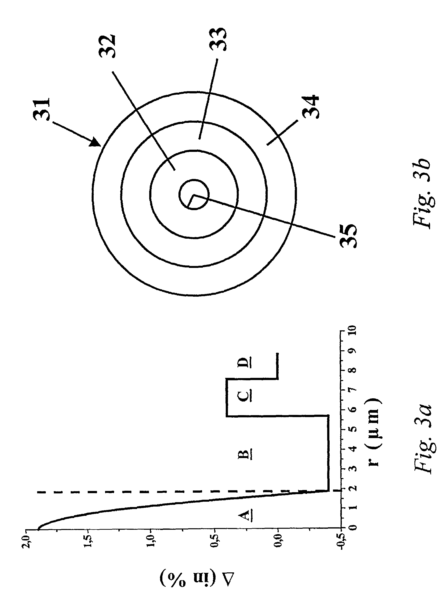
[0060]the substrate tube used for the production of the fiber with a refractive index profile according to FIG. 3a, is schematically represented in FIG. 3b. A more detailed description of the substrate tube and the method of its production follows below.

[0061]The substrate tube 31 has an outer diameter of 25 mm and a total wall thickness of 3 mm. The inner layer 32 of the substrate tube 31 is composed of fluorine-doped quartz glass which has a refractive index lower by 5.8×10⁻³ than that of pure quartz glass. The fluorine concentration in the core segment B is approximately 2% by weight and the layer thickness is 1.19 mm. This is followed by an intermediate layer 33 doped with about 10% by weight of GeO2 and also with 2% by weight of fluorine, which results in the above-mentioned increase of the normal refractive index of 0.4% in the core segment C. The layer thickness of the intermediate layer 33 is 0.95mm. The outer layer 34 of the substrate tube 31 has a layer thickness of 0.86 m...

second embodiment

[0065]a substrate tube for the production of a fiber with a refraction index according to FIG. 3a and a process for its production will be described below in more detail.

[0066]The substrate tube has an outer diameter of 25 mm and a total wall thickness of 3 mm. The inner layer of the substrate tube is composed of fluorine-doped quartz glass which has a refractive index lower by 5.8×10⁻³ than that of pure quartz glass. The fluorine concentration in the core segment B is approximately 1% by weight. The layer thickness is 1.19 mm. This is followed by an intermediate layer doped with about 5.4% by weight of GeO2 which results in the increase of the normal refractive index of Δ=0.4 in the core segment C shown in FIG. 3a The layer thickness of the intermediate layer is 0.95 mm. The outer layer of the substrate tube has a layer thickness of 0.86 mm and is composed of undoped quartz glass. In the case of the refractive index profile of the optical fiber obtained by using this substrate tube...


PUM

PropertyMeasurementUnit
refractive indexaaaaaaaaaa
transmission wavelengthaaaaaaaaaa
refractive indexaaaaaaaaaa

Abstract

On the basis of a known process for the production of a preform for an optical fiber for optical data transmission technology, the productivity of the process for the production of complex refractive index profiles is to be improved by providing a quartz glass substrate tube which exhibits different doping in radial direction, introducing a core glass made of synthetic quartz glass into the substrate tube and covering the substrate tube with a jacket tube. A substrate tube suitable therefor is also being provided which tube requires less core glass material for the production of the preform, whether during the internal deposition or for the core glass rod in the rod-in-tube technique. Regarding the process it is proposed according to the invention that a substrate tube be used which was obtained by vitrification of a porous tube-shaped SiO2 blank, the substrate tube being provided with a core glass layer which is produced in that to the first radial portion of the SiO2 blank there is added before the vitrification a first dopant which increases the refractive index of quartz glass. The substrate tube according to the invention has in the radial direction regions of different doping whereby it incorporates a core glass layer which has a refractive index of at least 1.459.

Description

RELATED APPLICATIONS[0001]This application is a continuation of U.S. patent application Ser. No. 09 / 440,413 filed Nov. 15, 1999, now abandonedFIELD OF THE INVENTION[0002]The invention concerns a process for the production of a preform for an optical fiber for optical data transmission technology, by providing a substrate tube of quartz glass which tube has different dopants in radial progression, by introducing a core glass of synthetic quartz glass, and by surrounding the substrate tube with a jacket tube.[0003]Furthermore, the invention concerns a substrate tube of quartz glass for the production of a preform for an optical fiber for optical data transmission technology, where the preform comprises a core glass which is surrounded by a mantle region of which region at least a part is provided in form of the substrate tube which tube has different dopants in radial direction.DISCUSSION OF THE PRIOR ART[0004]In general, preforms for optical fibers have a core which is surrounded by ...

Claims


Application Information

Patent Timeline
Patent Type & Authority Patents(United States)
IPC IPC(8): C03B37/018C03B19/14C03B37/012C03B37/02
CPCC03B37/01205C03B37/01211C03B37/01892C03B2203/36C03B2201/31C03B2203/22C03B2201/12
Inventor SCHAPER, HARTWIGTREBER, NORBERTHUMBACH, OLIVERHAKEN, UWEJABLONOWSKI, DONALD PAUL
Owner HERAEUS TENEVO
Learn More