
Asynchronous debug interface

a debug interface and asynchronous technology, applied in the field of microcontrollers, can solve the problems of synchronization of inability to effectively detect any problems, and inability to effectively detect problems, etc., and achieve the effect of synchronizing the mcu and the debug module, clock and handshake signals, and dedicated data

Active Publication Date: 2006-08-08
NORTH STAR INNOVATIONS
View PDF6 Cites 20 Cited by
  • Summary
  • Abstract
  • Description
  • Claims
  • Application Information

AI Technical Summary

Benefits of technology

"The invention provides a method and apparatus for debugging a microcontroller using a three level signal. This allows for more efficient and accurate debugging of microcontrollers. The technical effects of the invention include improved debugging of microcontrollers and reduced debugging time."

Problems solved by technology

As the performance of MCUs increases and the cost simultaneously decreases, it is increasingly necessary to put software debug logic on-chip.
This becomes a problem as IC designers never know what frequency a customer might use, and a clocking signal is important to keep the two modules synchronized.
However, problems arise when the clock in the BDM becomes out of sync with the clock in the MCU.
If this situation arises, the BDM cannot effectively detect any problems that may be present.
Thus, synchronization of the MCU and the debug module, without dedicated data, clock, and handshake signals, is a fundamental problem.

Method used


Image

  • Asynchronous debug interface
  • Asynchronous debug interface
  • Asynchronous debug interface

Examples


Embodiment Construction

[0019]The invention and the various features and advantageous details thereof are explained more fully with reference to the nonlimiting embodiments that are illustrated in the accompanying drawings and detailed in the following description.

[0020]The invention can include a background debug interface for use with microcontroller units. The invention can also include the use of a tri-state waveform.

[0021]A practical application of the invention that has value within the technological arts is that it can be used to debug most low cost MCUs. It is not limited to asynchronous logic and is only a small incremental cost from the debugging mechanisms currently in use.

[0022]An asynchronous debug module, representing an embodiment of the invention, can be cost effective and advantageous. The invention eliminates a problem that the clock of a MCU and debug module must be synchronized even when the clock of the MCU is variable or unknown. (i.e. a PLL (phase locked loop) is used). According to ...


PUM


Abstract

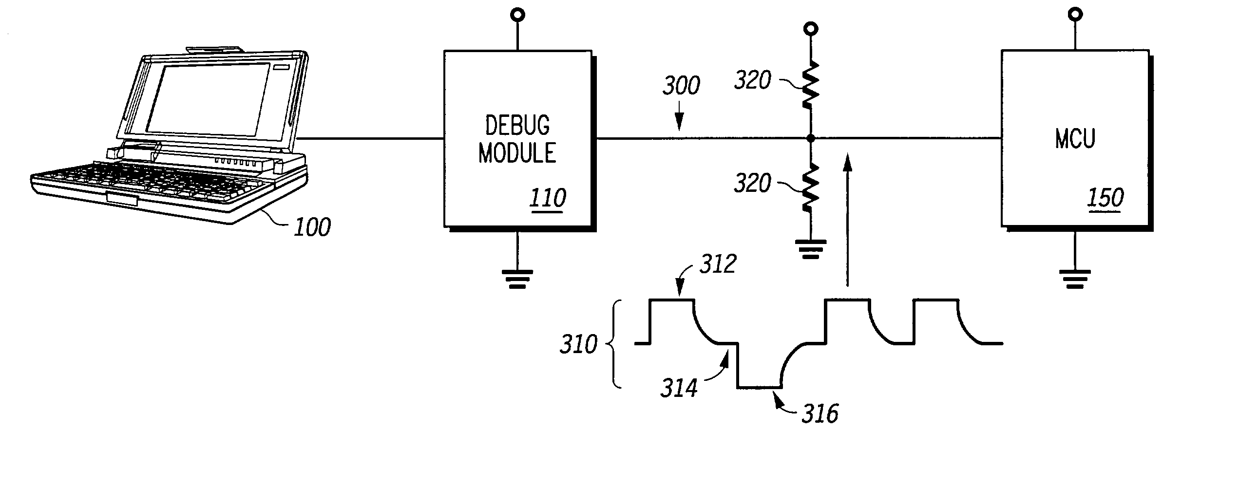
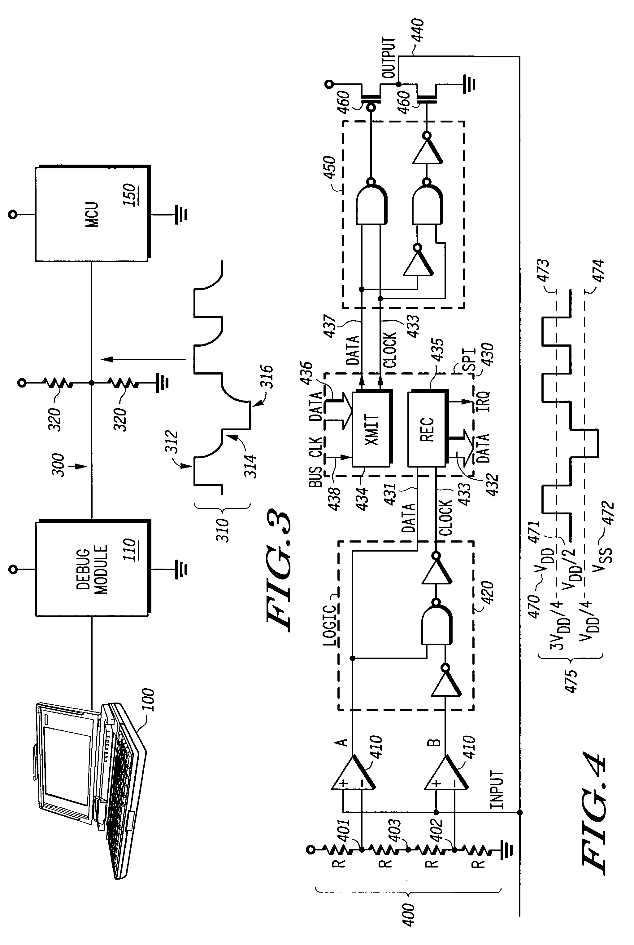
Apparatus and methods are described for a background microcontroller debugger. A method to debug a microcontroller includes sending a three level signal from a debug module, receiving the three level signal at a single pin on an MCU, sending a second three level signal from the single pin on the MCU, and receiving the second three level signal at the debug module. An apparatus to debug a microcontroller includes a tri-statable pad driver to transmit a three level signal, a reference voltage divider coupled to the tri-statable pad diver, a plurality of voltage comparators to receive the three level signal, a resistive voltage divider to maintain thresholds for the plurality of voltage comparators, and a plurality of logic elements coupled to the plurality of voltage comparators to receive the three level signal.

Description

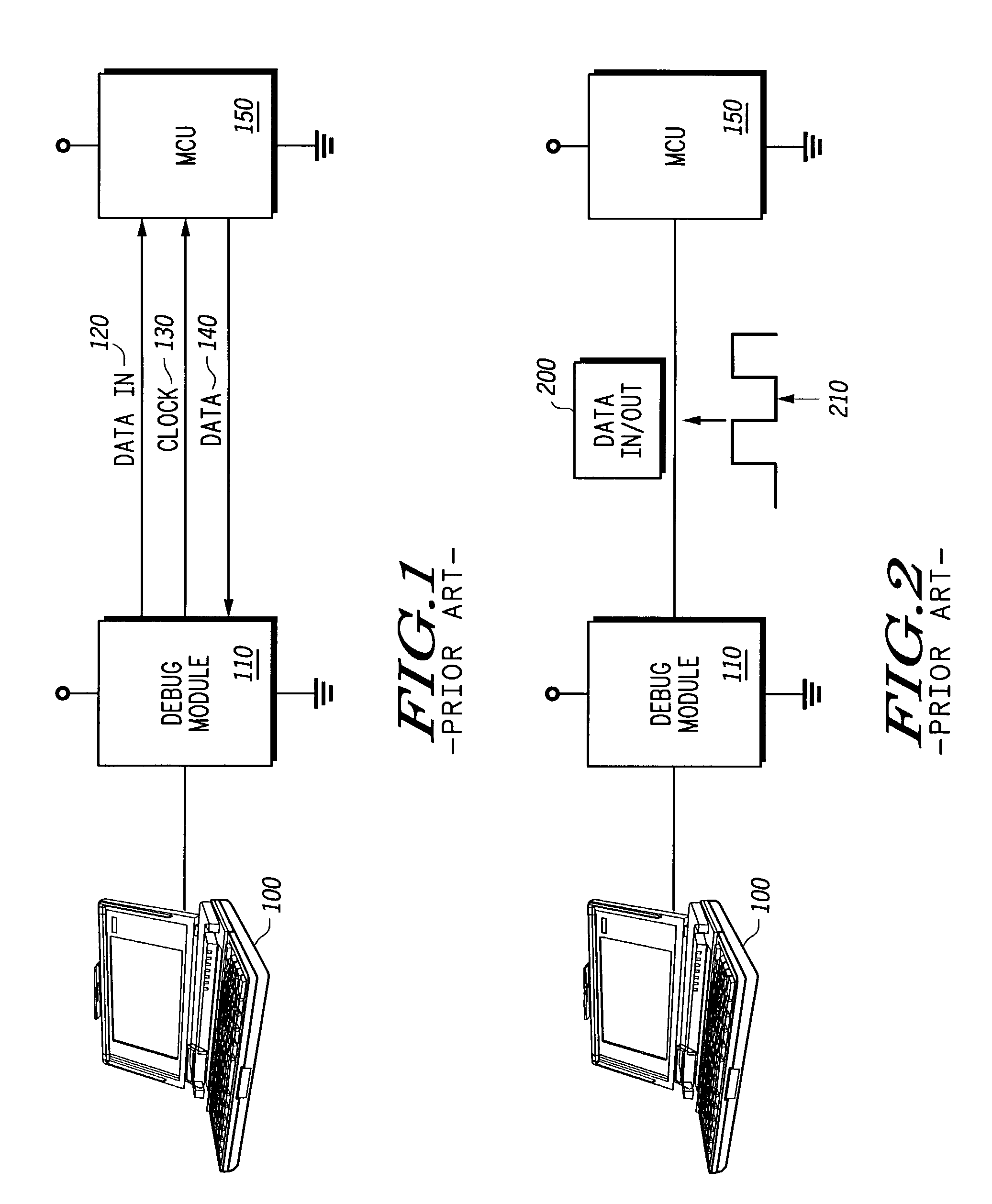
BACKGROUND OF THE INVENTION[0001]1. Field of the Invention[0002]The invention relates generally to the field of microcontrollers. More particularly, the invention relates to debug interfaces for microcontrollers.[0003]2. Discussion of the Related Art[0004]Background debug, which aids in the development of software in microcontrollers (MCUs), has been in existence since about 1990 and has grown in sophistication. Debug is essential for the software development of most modern MCUs. It usually utilizes a synchronous serial data protocol.[0005]As shown in FIG. 1, a control device, such as a computer 100, is linked to a debug module 110 to debug the software in the MCU 150. A “data in” signal 120 and a clock signal 130 are sent simultaneously from the debug module 110 to the MCU 150, and a data signal 140 is sent back to the debug module 110 from the MCU 150. This data signal 140 is analyzed to detect and correct possible problems in the software in the MCU 150.[0006]FIG. 2 illustrates a...

Claims


Application Information

Patent Timeline
Patent Type & Authority Patents(United States)
IPC IPC(8): G01R31/28H04L1/22
CPCH04L1/22
Inventor BURCH, KENNETH R.
Owner NORTH STAR INNOVATIONS
Learn More