DC/DC converter

a converter and dc technology, applied in the field of dc/dc converters, can solve the problems of inconvenient use, inability to use step-up voltage regulation, and difficulty in adjusting the voltage of the converter, and achieve the effect of simple method of dc voltage conversion

Active Publication Date: 2006-08-01
TEXAS INSTR INC
View PDF6 Cites 20 Cited by
  • Summary
  • Abstract
  • Description
  • Claims
  • Application Information

AI Technical Summary

Problems solved by technology

One problem associated with the simple circuit as shown in FIG. 1 is that it can only be put to use for step-up but not for step-down voltage regulation.
The circuit as shown in FIG. 1 is thus not suitable e.g. for battery-powered devices in which the battery voltage during the lifetime of the battery initially exceeds the wanted operating voltage of a device powered with a voltage regulator so that it needs to be bucked (stepped down), and later after a certain discharge of the battery, drops below this wanted voltage so that it needs to be boosted (stepped up).
For such applications, only relatively complicated converters such as buck+boost or SEPIC converters come into question necessitating a costly array of external components.

Method used


Image

  • DC/DC converter
  • DC/DC converter

Examples


Embodiment Construction

[0013]FIG. 1 illustrates a DC / DC converter circuit as described at the outset, serving to explain the gist of the invention.

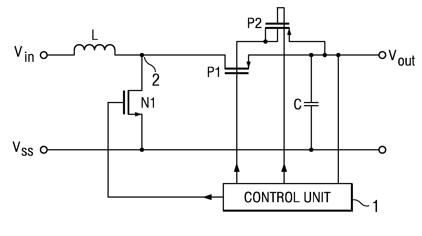
[0014]FIG. 2 illustrates a preferred embodiment of a DC / DC converter in accordance with the invention in the form of its circuit diagram.

[0015]The circuit as shown in FIG. 2 has a similar configuration to that as shown in FIG. 1. The configuration of the circuit as shown in FIG. 2 will first be described.

[0016]Referring now to FIG. 2, there is illustrated how the circuit includes an inductance L also termed choke. Applied to the one terminal of the inductance is the input voltage Vin of the DC / DC converter which may be furnished e.g. by a battery. The other terminal of the inductance L is connected to the drain of a NMOS-FET N1 whose source is connected to the reference potential which in the present example includes the ground potential Vss. Instead of the first NMOSFET N1, some other controllable switch, e.g. a bipolar transistor may also be used.

[0017]The ot...


PUM


Abstract

The invention relates to a DC / DC converter including an input to which an input voltage Vin is applied, a inductance L whose one terminal is connected to the input, a first controllable switch N1 via which the other terminal of the inductance is connectable to a reference potential Vss, a second controllable switch P1 via which the other terminal of the inductance is connectable to the output of the converter, and a regulator circuit 1 configured so that it is able to control the two switches in regulating the output voltage of the DC / DC converter to a predetermined wanted value. The second controllable switch is a PMOS-FET. The regulator circuit is configured so that when the input voltage is higher than the desired value of the output voltage, the gate of the PMOS-FET is permanently connected to a voltage which is larger than the difference between the input voltage and the threshold voltage of the PMOS-FET, it connecting the back gate of the PMOS-FET permanently to a voltage which is larger than the expression input voltage plus threshold voltage of the PMOS-FET minus the diode voltage of a pn junction of the PMOS-FET and timing the first controllable switch with a specific duty cycle so that the output voltage attains the wanted value. The converter in accordance with the invention now permits achieving both an increase and decrease in the input voltage. It can be put to use preferably in conjunction with battery-powered devices for which a wanted voltage is specified.

Description

RELATED APPLICATION[0001]The present application is based on priority of German Patent Application No. 102 49 802.4, filed on Oct. 24, 2002.FIELD OF THE INVENTION[0002]The present invention relates to a DC / DC converter as well as to a method for DC voltage conversion.BACKGROUND OF THE INVENTION[0003]Belonging to the simplest prior art DC / DC converters are the so-called inductor-type converters serving to achieve a practically lossless potential conversion of a DC voltage into a desired output DC voltage with the aid of an inductance. One of the basic types of the inductor-type converters is the so-called step-up converter with which an input DC voltage can be converted into a boosted output DC voltage whose value exceeds that of the input DC voltage.[0004]One such step-up converter is described e.g. in the German book on switching power supplies “Schaltnetzteile” by Udo Leonhard Thiel, 2nd Edition, published 1998 by Franzis-Verlag, on pages 34 et seq. In this described step-up conve...

Claims


Application Information

Patent Timeline
Patent Type & Authority Patents(United States)
IPC IPC(8): G05F1/613H02M3/158
CPCH02M3/1582H02M2001/0045H02M1/0045
Inventor KIRCHNER, JOERGKELLER, THOMASSCHIMPFLE, CHRISTIAN
Owner TEXAS INSTR INC
Why Eureka
Try Eureka