
Pipe centralizer and method of attachment

a centralizer and pipe technology, applied in the field of centralizers, can solve the problems of changing the performance requirements of the casing centralizer employed, placing the severest structural demands on the centralizer, and being relatively expensiv

Inactive Publication Date: 2006-08-01
NABORS DRILLING TECH USA INC
View PDF29 Cites 44 Cited by
  • Summary
  • Abstract
  • Description
  • Claims
  • Application Information

AI Technical Summary

Benefits of technology

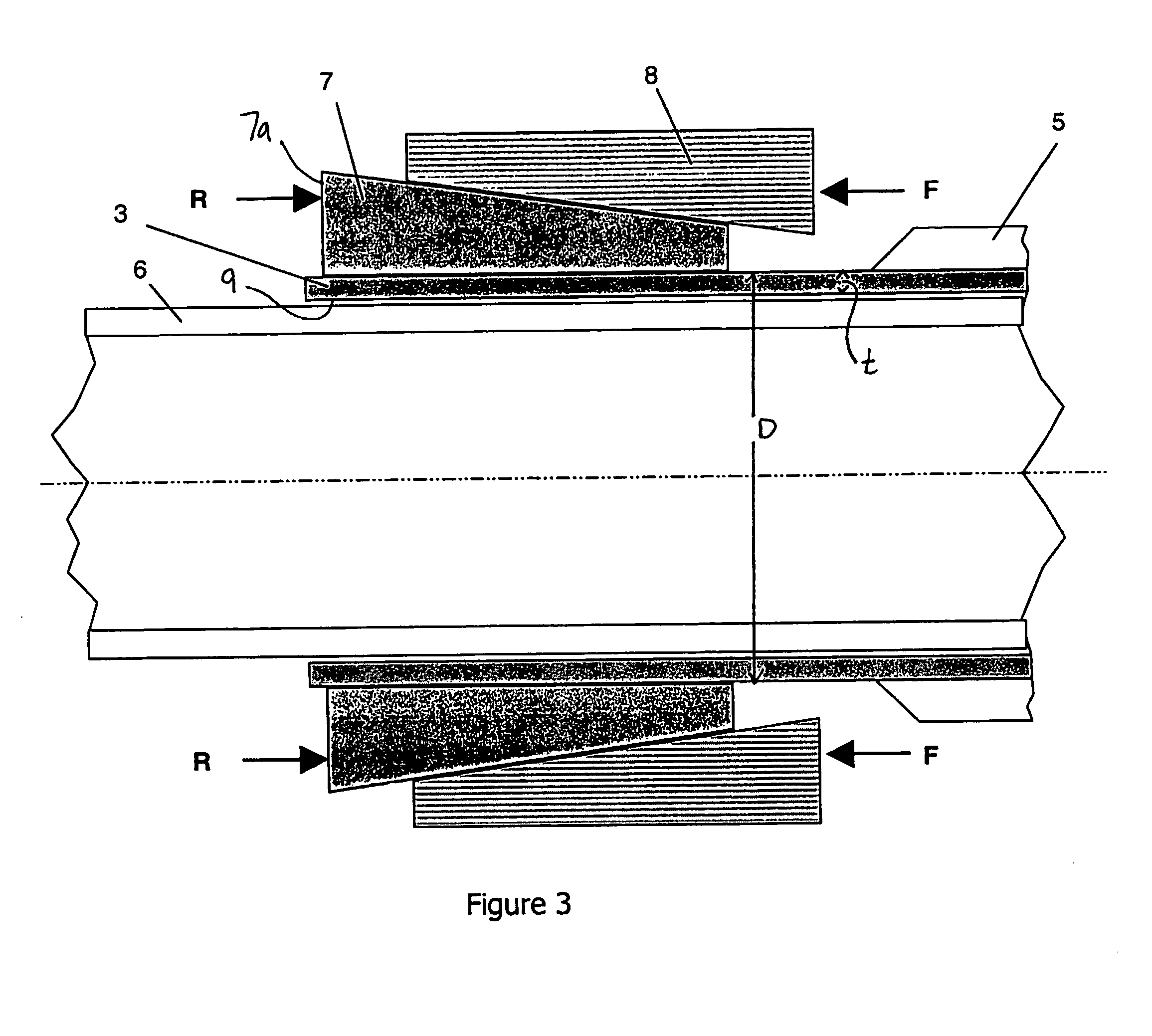
[0008]A crimped centralizer has been invented for installation on metal pipe, such as would be useful in well bore drilling and casing operations. The present invention provides a centralizer having a cylindrical body which when coaxially placed over a metal pipe and substantially radially inwardly displaced at a plurality of points (i.e. crimped) about the circumference of a section of the cylindrical body, attaches to the pipe to create a connection having structurally significant axial and torque load transfer capacity. When crimped according to the methods of the present invention, the load transfer capacity of the connection between the centralizer and the pipe can be arranged to substantially prevent significant relative movement of the centralizer on the pipe under loads that may be encountered when using one or more of the metal pipes as components of a tubular string used for drilling or completing well bores.
[0016]Preferably, the inward, substantially radially directed force is not so great that the drift diameter of the metal pipe is excessively reduced. Frictional forces enabled by the interference fit at the inwardly displaced section provide the mechanism by which structurally significant axial and torsional load may be transferred between the centralizer and metal pipe without slippage therebetween.
[0020]A further purpose of the present invention is to facilitate the frictional engagement of the crimped centralizer to the thick-wall pipe. To meet this purpose, in one embodiment of the present invention the inside surface of centralizer, at least over the section to be crimped, is provided with a roughened surface finish. In a further embodiment, a friction enhancing material such as a grit epoxy mixture is disposed in the interfacial region of the crimped section. Similarly, various bonding materials may be disposed in the interfacial region prior to crimping to act as glues augmenting the frictional aspects of the connection once their shear strength is developed after setting.

Problems solved by technology

Drilling places the severest structural demands on centralizers since they must survive extended periods of time in rotating contact with the borehole wall.
To meet these requirements drilling centralizers are typically integral with the drill string, and may be relatively expensive since they are reused.
These requirements have led to casing centralizers that attached to the exterior of the connection by means having little or no torsional and limited axial load transfer capacity.
However, using casing to both drill and complete the well changes the performance requirements of the casing centralizers employed.
Casing centralizers, as employed in the prior art, typically rotate relative to the casing body under application of extended rotation required for drilling, causing wear of the centralizer, casing or both, leading to potential failure of the centralizer or casing.
Adapting the integral centralizer architecture employed for drill string centralizers, while providing a technically feasible means to centralize casing for drilling, is costly and more complex to implement than simply attaching to the casing exterior.

Method used


Image

  • Pipe centralizer and method of attachment
  • Pipe centralizer and method of attachment
  • Pipe centralizer and method of attachment

Examples


Embodiment Construction

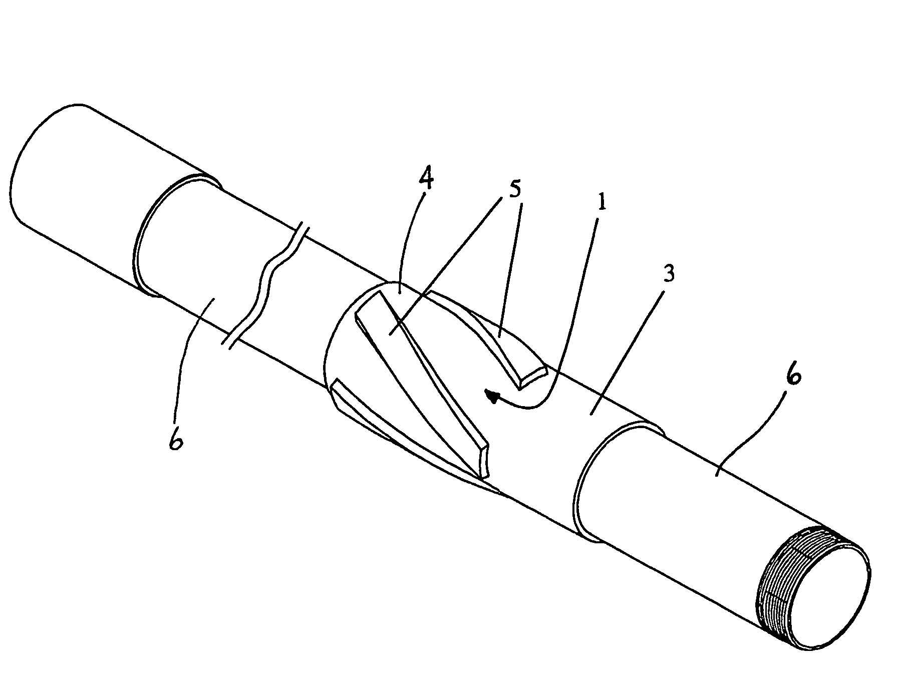
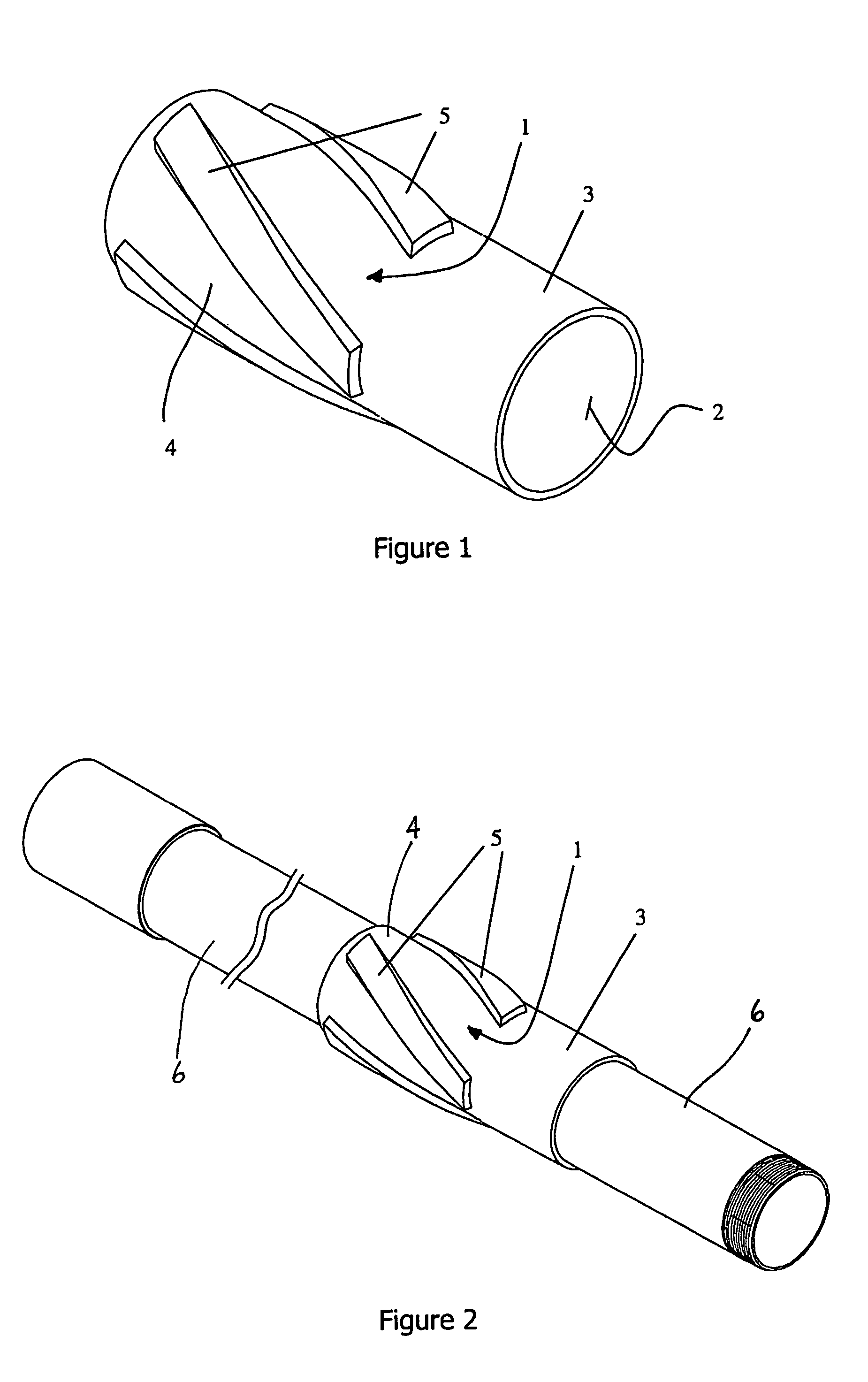
[0026]According to the present invention, a centralizer is provided as shown in FIG. 1, and a method of crimping it to a thick-wall metal pipe when placed on the pipe as shown in FIG. 2.

[0027]Referring to FIG. 1, the centralizer is provided having a metal body 1 containing an internal bore 2, a cylindrical end 3 forming a section suitable for crimping, and a centralizing section 4 on which ribs 5 are placed.

[0028]The cylindrical end and the centralizing section are formed integral on the body and the internal bore passes through both of them. While the crimpable section in the illustrated embodiment is cylindrical end, it is to be noted that the crimpable section can be formed intermediate a pair of centralizing sections, if desired, rather than on an end. Also, it is to be noted that more than one crimpable section and more than one centralizing section can be provided on the centralizer, as desired.

[0029]Ribs 5 are evenly spaced around the centralizing section. There are at least ...


PUM

PropertyMeasurementUnit
Thicknessaaaaaaaaaa
Diameteraaaaaaaaaa
Stress optical coefficientaaaaaaaaaa

Abstract

A crimpable centralizer has been invented for installation on pipe, such as would be useful in well bore drilling and casing operations. The present invention provides a centralizer having a cylindrical body which when coaxially placed over a pipe and substantially radially inwardly displaced at a plurality of points (i.e. crimped) about the circumference of a section of the cylindrical body, attaches to the pipe to create a connection having structurally significant axial and torque load transfer capacity. When crimped according to the methods of the present invention, the load transfer capacity of the connection between the centralizer and the pipe can be arranged to substantially prevent significant relative movement of the centralizer on the pipe under loads that may be encountered when using one or more of the pipes as components of a tubular string used for drilling or completing well bores.

Description

FIELD OF THE INVENTION[0001]The present invention relates to centralizers attached to pipe placed in boreholes. The invention discloses centralizers and methods of attachment to enable transfer of structurally significant axial and torsional loads between the centralizer and pipe.BACKGROUND OF THE INVENTION[0002]The processes of drilling and completing well bores in earth materials using tubular strings are frequently benefited if the tubular string is prevented from fully eccentering and generally contacting or laying against the borehole wall. Numerous devices, typically referred to as centralizers, are employed to provide this function of reducing eccentricity, or centralizing, the tubular string within the borehole. These devices are configured to economically meet a variety of drilling and completion applications.[0003]Within the context of petroleum drilling and well completions, wells are typically constructed by drilling the well bore using one tubular string, largely compri...

Claims


Application Information

Patent Timeline
IPC IPC(8): E21B17/10E21B7/20E21B29/00E21B43/10
CPCE21B7/20E21B17/1078E21B43/10E21B29/00Y10T29/49908
Inventor SLACK, MAURICE WILLIAM
Owner NABORS DRILLING TECH USA INC
Learn More