
Structure of connecting wire to element-containing unit

a technology of element-containing units and wires, which is applied in the direction of connection contact materials, multiple-port networks, coupling device connections, etc., can solve the problems of insufficient fixed condition of each capacitor, low production efficiency, and damage to the element, so as to prevent damage and separation of the element, and production efficiency can be enhanced

Active Publication Date: 2006-07-25
YAZAKI CORP
View PDF32 Cites 4 Cited by
  • Summary
  • Abstract
  • Description
  • Claims
  • Application Information

AI Technical Summary

Benefits of technology

The invention provides a structure for connecting wires to element-containing units, which prevents damage and separation of the element. The structure includes an internal resin cover that separates the intermediate portion of the wire from the element, and a wire-side terminal that is connected to the intermediate portion of the wire and extends into the element receiving space. The wire-side terminal is connected to the relay terminal and the grounding terminal, which form the circuit. The internal resin cover, relay terminal, and grounding terminal are mounted on the upper and lower resin covers, and the connection legs of the element are inserted into the element connection portions of the relay terminal and grounding terminal. The invention also provides a wire reception portion and an element holding portion for easy assembly and mounting of the element-containing unit. The invention improves production efficiency and simplifies the construction of the circuit.

Problems solved by technology

In such a case, there is encountered a problem that a wrong operation is caused by the inputted noises.
In the above conventional technique, when the intermediate portion of the wire, received in an internal space formed by the upper and lower resin covers, is not extended straight, there is a possibility that the following disadvantages are encountered.
Namely, there is a possibility that the bent intermediate portion of the flexible wire interferes with the chip capacitor to damage the same, and in some cases there is a possibility that the chip capacitor is separated from the conducting portion.
Therefore, it is necessary to beforehand straighten the intermediate portion of the wire which is to be received in the resin covers although this is cumbersome.
Moreover, the above conventional technique is directed to the structure in which the conducting portions are formed by applying the plating to the lower resin cover made of a resin, and therefore the production process requires many steps, which invites a problem that the efficiency of the production is very low.
Furthermore, in this structure, the chip capacitors are fixed by applying the plating, and therefore there is a fear that the fixed condition of each capacitor becomes insufficient.

Method used


Image

  • Structure of connecting wire to element-containing unit
  • Structure of connecting wire to element-containing unit
  • Structure of connecting wire to element-containing unit

Examples


Embodiment Construction

[0036]The present invention will now be described with reference to the drawings.

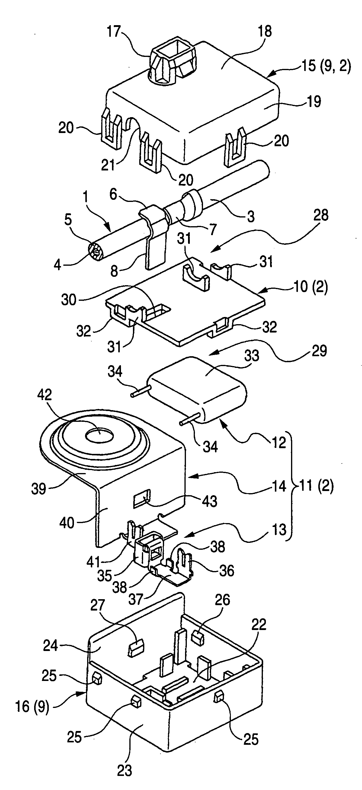
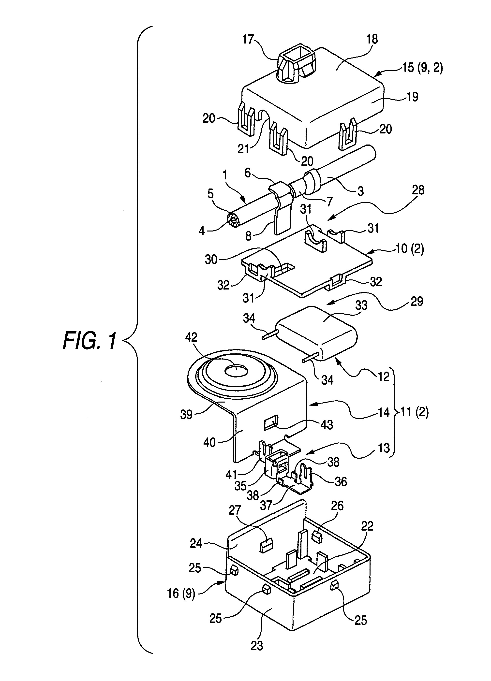
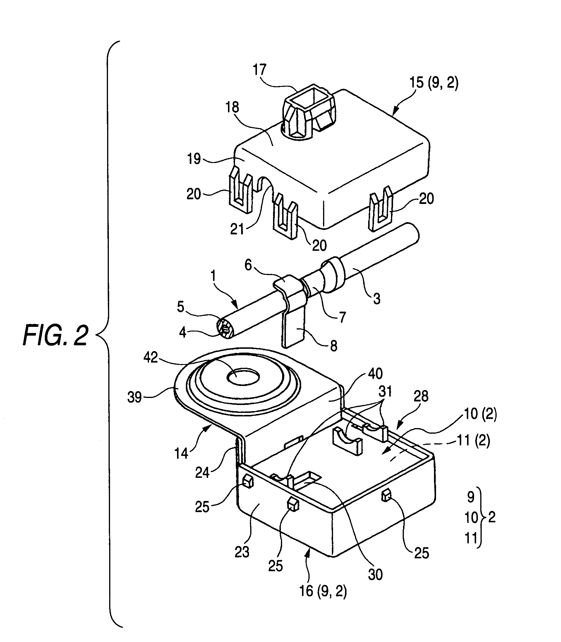
[0037]FIG. 1 is an exploded, perspective view showing one preferred embodiment of a structure of the invention for connecting a wire to an element-containing unit, FIG. 2 is a perspective view, showing a condition before an intermediate portion of the wire is received in the unit, and FIG. 3 is a perspective view, showing a condition in which the element is received in the unit.

[0038]In FIG. 1, reference numeral 1 denotes the wire of the known type. Reference numeral 2 denotes the element-containing unit to be connected to the intermediate portion 3 of the wire 1. In this embodiment, the element-containing unit 2 is designed to function as a noise filter as will be hereafter more fully described (However, the unit 2 is not always limited to such a noise filter.). In the following description, the wire 1 is installed in a vehicle such as an automobile, and the element-containing unit 2 is retainingly eng...


PUM


Abstract

An insulative internal resin cover is provided to partition an internal space of upper and lower insulative resin covers into a wire receiving space and an element receiving space. A wire-side terminal is provided at an intermediate portion of a wire, and is electrically connected to a conductor of the wire. When the intermediate portion of the wire is located in the wire receiving space, the wire-side terminal is inserted from the wire receiving space into the element receiving space through a terminal insertion hole formed in the internal resin cover, and is connected to a circuit including an element received in the element receiving space.

Description

BACKGROUND OF THE INVENTION[0001]1 . Field of the Invention[0002]This invention relates to a structure of connecting a wire to an element-containing unit having an element contained in an internal space of upper and lower insulative resin covers.[0003]2 . Related Art[0004]For example, there are occasions when transmission noises with a high-frequency component from a noise source such as a horn and a wiper motor, external noises from a neon glow lamp or the like, induction noises and the like are inputted through a wire into various sensors provided on an automobile. In such a case, there is encountered a problem that a wrong operation is caused by the inputted noises. It has heretofore been proposed to provide a noise prevention device (as disclosed in JP-A-2-295199 (Page 2, FIGS. 1 to 5)) at an intermediate portion of the wire.[0005]The noise prevention device, disclosed in JP-A-2-295199, includes an upper resin cover and a lower resin cover which cooperate with each other to cove...

Claims


Application Information

Patent Timeline
Patent Type & Authority Patents(United States)
IPC IPC(8): H01R13/66
CPCH01R4/2429H01R4/64H01R13/6625H01R2201/26H01R13/73H01R13/506
Inventor NAGAOKA, YASUTAKAYAMAGUCHI, TORUMAENO, SEIGEN
Owner YAZAKI CORP
Learn More