Eureka AIR delivers breakthrough ideas for toughest innovation challenges, trusted by R&D personnel around the world.

PWM driving apparatus

a driving apparatus and driving motor technology, applied in the direction of electric controllers, instruments, ignition automatic control, etc., can solve the problem of fluctuation in the amount of electromagnetic noise generation, and achieve the effect of simplifying the circuit structur

Inactive Publication Date: 2006-07-18
CALSONIC KANSEI CORP
View PDF15 Cites 25 Cited by
  • Summary
  • Abstract
  • Description
  • Claims
  • Application Information

AI Technical Summary

Benefits of technology

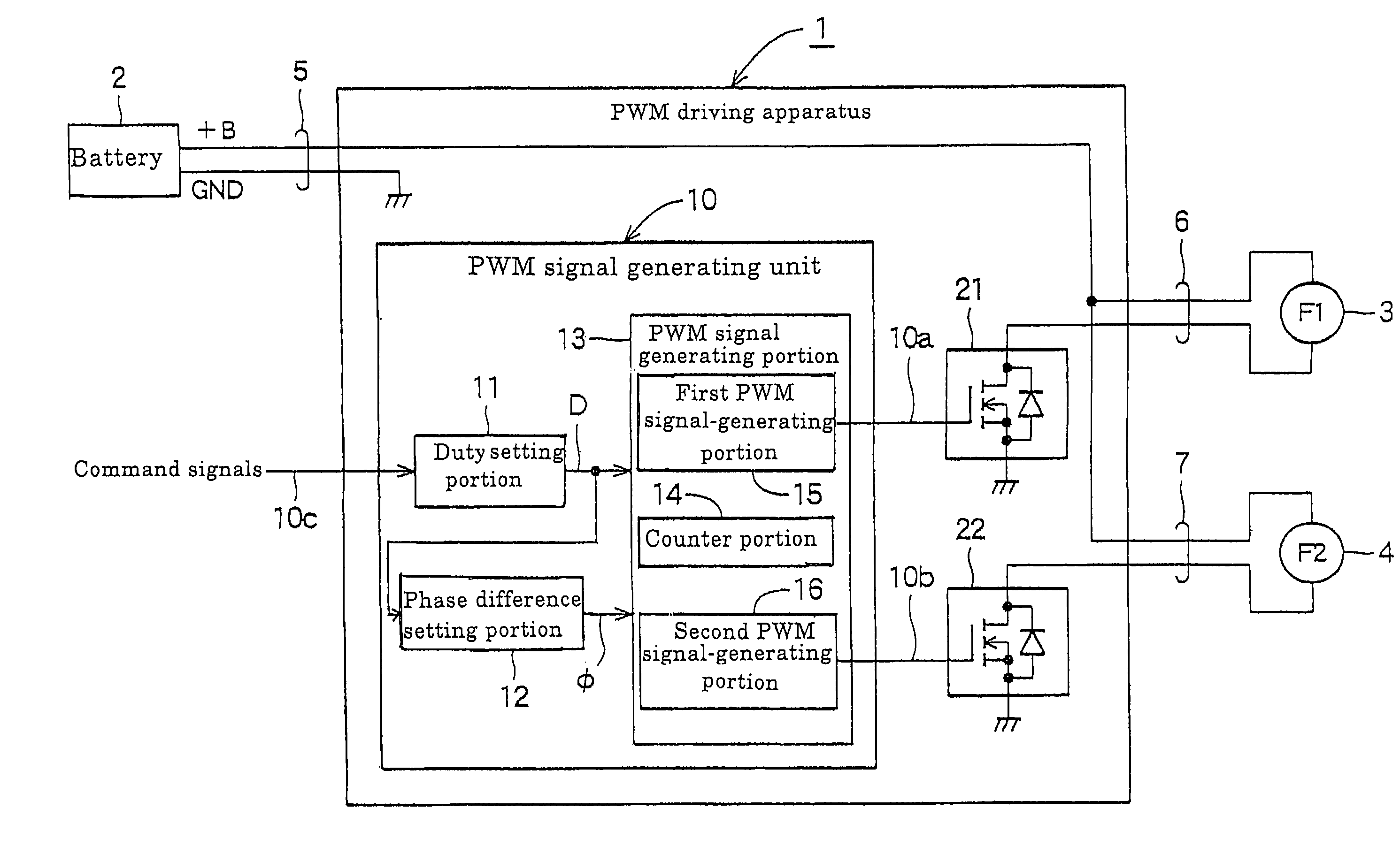
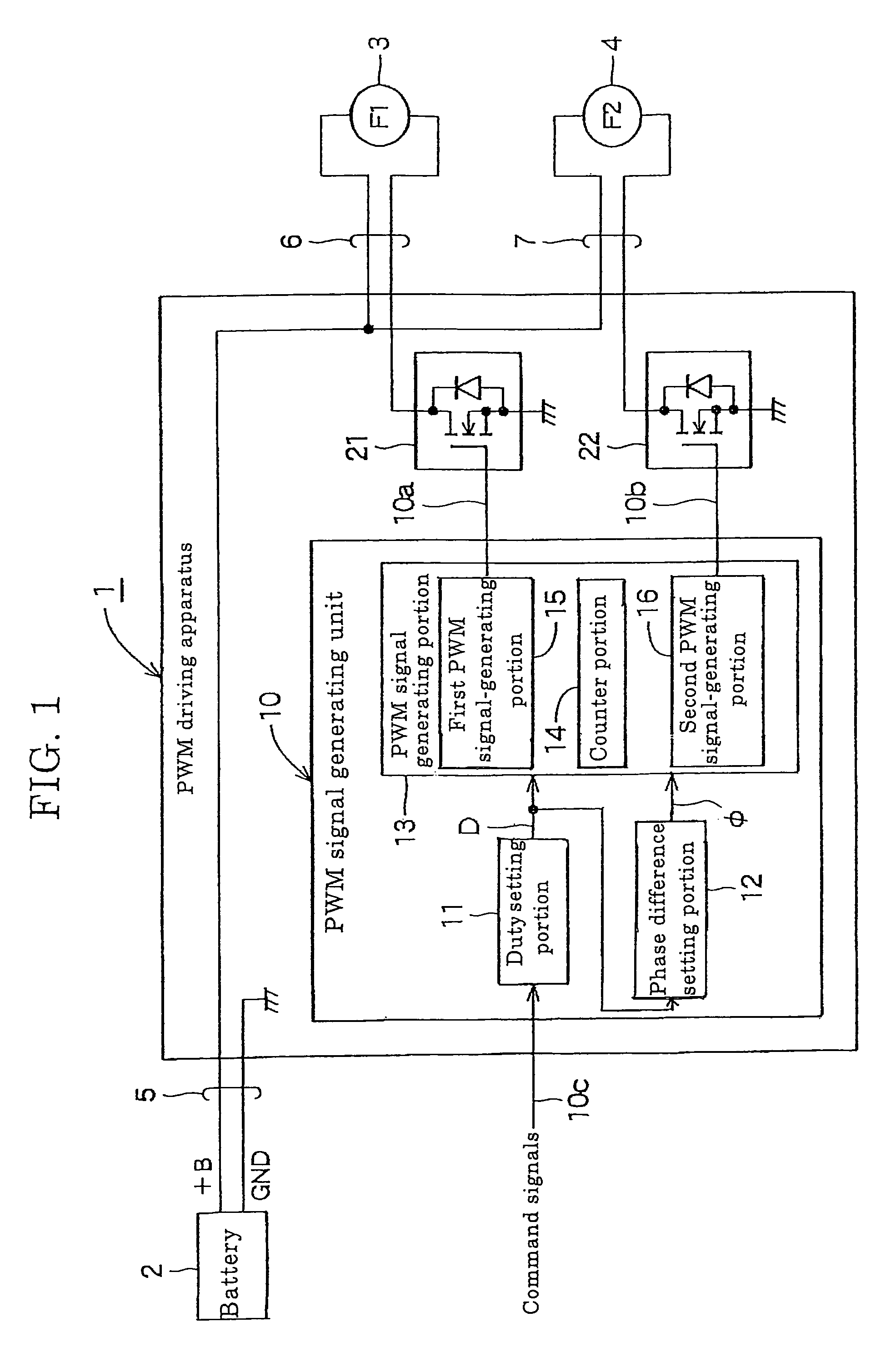
[0010]The PWM driving apparatus according to the present invention generates the first and the second PWM signals of the previously set phase difference based on the duties of the PWM signals and performs a PWM control of power supplying to each of the respective loads. Generation of an electromagnetic noise can be made less throughout the entire range of the duties by previously setting the phase difference in which the generation of the electromagnetic noise becomes less corresponding to the duty. Also, since the PWM signal generating unit comprises the duty setting portion for setting the duty based on the command signals, the phase difference setting portion for setting the phase difference based on the duty, and the PWM signal generating portion for generating the first and the second PWM signals based on the duty and the phase difference, it becomes easy to generate the respective PWM signals by software control, for example, by using a microcomputer.
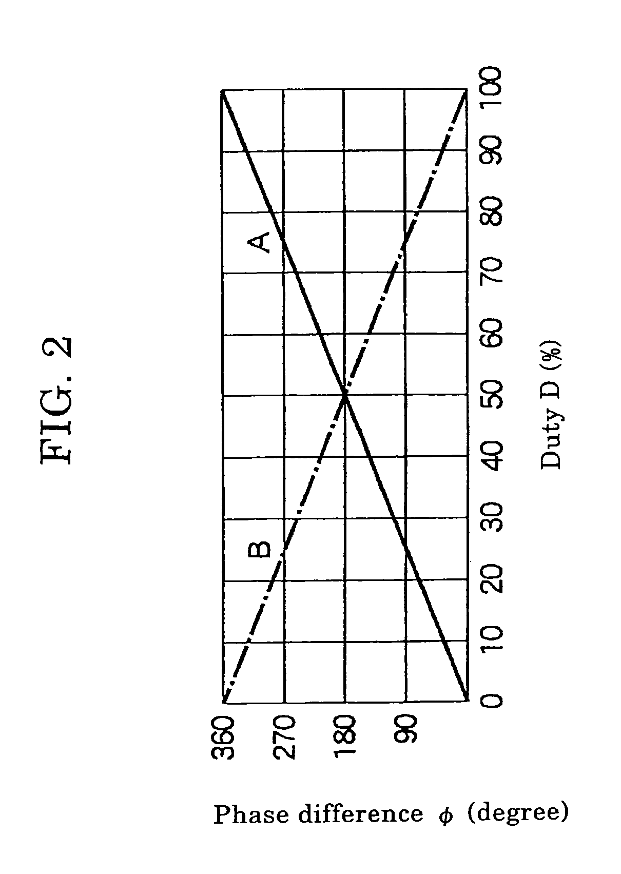
[0013]φ (degree)=360 (degree)−{360 (degree)×D (%) / 100 (%)}, the rising timing of first PWM signals and the falling timing of the other PWM signals can be coincided with each other. Accordingly, it is possible to reduce variations in a load current, and thus the generation of the electromagnetic noise due to the variations in the load current can be reduced.
[0015]The another PWM driving apparatus according to the present invention is structured to generate the first PWM signals based on the carrier signals, and to generate the second PWM signals based on the reversal carrier signals. Therefore, a circuit structure can be simplified since a single carrier signal generator suffices. In addition, by providing the carrier signals as the saw-tooth wave pattern, it is possible to generate the first and the second PWM signals with the phase difference which corresponds to the duty of the PWM signals.
[0016]Furthermore, when each of the loads is a motor fan for being mounted in a vehicle, because the electromagnetic noise (conduction noise and radiated noise) generated due to a PWM operation of each of the motor fans can be lowered, noise which interfuses to an in-vehicle radio and the like can also be reduced.

Problems solved by technology

Accordingly, when an amount of electric power to be supplied to the load is varied (more specifically, when the duty of the PWM signals is varied), the amount of generation of the electromagnetic noise fluctuates, thus there is a case that the electromagnetic noise may be heard from a car-mounted radio as a disturbing noise.

Method used


Image

  • PWM driving apparatus
  • PWM driving apparatus
  • PWM driving apparatus

Examples


first embodiment

[0023]FIG. 1 is a block diagram showing a PWM driving apparatus according to the present invention. The PWM driving apparatus 1 shown in FIG. 1 receives supplying of an electric power from a battery 2 mounted in a vehicle and operates two motor fans 3, 4 (for example, a fan F1 for cooling a radiator and a fan F2 for cooling a condenser) as first and second loads, respectively, under a PWM control. In addition, reference numeral 5 denotes a battery power-supplying cable, and reference numerals 6, 7 denote power-supplying cables for the respective motor fans. Reference numeral +B denotes an anode of the battery 2, and reference numeral GND denotes a cathode (ground) of the battery 2.

[0024]This PWM driving apparatus 1 includes a PWM signal generating unit 10 which generates first PWM signals 10a and second PWM signals 10b based on command signals 10c, a first load-driving circuit 21 which performs switching of the electric power to be supplied to the first motor fan 3 on the basis of t...

second embodiment

[0040]FIG. 4 is a block diagram of a PWM driving apparatus according to the present invention. The PWM driving apparatus 1A shown in FIG. 4 receives the supplying of the electric power from a battery 2 mounted in the vehicle and operates two motor fans 3, 4 (for example, a fan F1 for cooling the radiator and a fan F2 for cooling the condenser) as first and second loads, respectively, under the PWM control. Meanwhile, reference numeral 5 denotes a batter-power supplying cable, and reference numerals 6 and 7 denote power-supplying cables for the motor fans. Reference numeral +B denotes an anode of the battery 2, and reference numeral GND denotes a cathode (ground) of the battery 2.

[0041]This PWM driving apparatus 1A includes a PWM signal generating unit 30 which generates first PWM signals 30a and second PWM signals 30b based on command signals 30c, a first load-driving circuit 21 which performs switching of the electric power to be supplied to the first motor fan 3 on the basis of th...


PUM


Abstract

When a PWM signal generating unit (10) sets a duty D of a PWM signal based on command signals (10c), the PWM signal generating unit (10) sets a phase difference φ between each of the PWM signals based on a relation formula of φ (degree)=360 (degree)×D (%) / 100 (%), and generates and outputs first PWM signals (10a) and second PWM signals (10b) in which the duty is D (%) and the phase difference is φ (degree). The first PWM signals (10a) and the second PWM signals (10b) are respectively supplied to a first load driving circuit (21) and a second load driving circuit (22) to operate a first motor fan (3) and a second motor fan (4) by a PWM control, respectively.

Description

BACKGROUND OF THE INVENTION[0001]1. Field of the Invention[0002]The present invention relates to a PWM driving apparatus which drives two loads connected in parallel to a power source by a PWM (Pulse Width Modulation) control.[0003]2. Description of the Prior Art[0004]Heretofore, there is described, for example in JP-A 2002-43910, a load controlling device which drives a plurality of loads connected in parallel to a power source. Such a load controlling device is of a pulse width modulation (PWM) control system for simultaneously driving first and second loads (for example, headlights) connected to the power source (for example, in-vehicle battery). In addition, this load controlling device includes first and second switching elements for applying power to the first and second loads respectively, and a controlling circuit which outputs first PWM signals to allow the first switching element to be turned ON and OFF upon receipt of signals for commanding driving and second PWM signals ...

Claims


Application Information

Patent Timeline
Patent Type & Authority Patents(United States)
IPC IPC(8): H02P7/06F01P5/04F01P7/04F04D27/00F04D29/66H02P5/68H03K7/08
CPCH02P5/68H03K7/08H02P7/29
Inventor SUNAGA, HIDEKIARAKI, FUTOSHITANAKA, KAORUTAKAHASHI, EIJI
Owner CALSONIC KANSEI CORP
Why Eureka
Eureka Blog
Learn More