
Image display system and image display methods

a display system and image technology, applied in the field of image display systems, can solve the problems of insufficient response speed of pi cells and so-called color breakup, and achieve the effect of increasing processing speed

Inactive Publication Date: 2006-07-18
KK TOSHIBA
View PDF4 Cites 6 Cited by
  • Summary
  • Abstract
  • Description
  • Claims
  • Application Information

AI Technical Summary

Benefits of technology

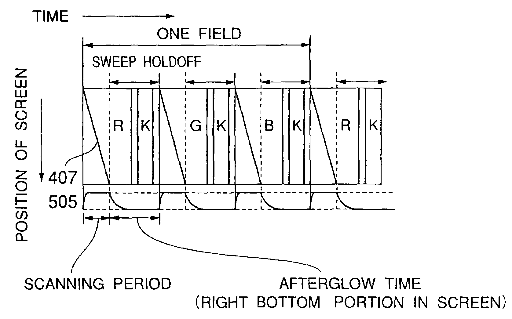
[0008]It is therefore an object of the present invention to eliminate the aforementioned problems and to provide an image display system and image display method, which can ensure a sufficient response time of cells of a liquid crystal color shutter in a time sharing display system for reducing a color breakup interference.
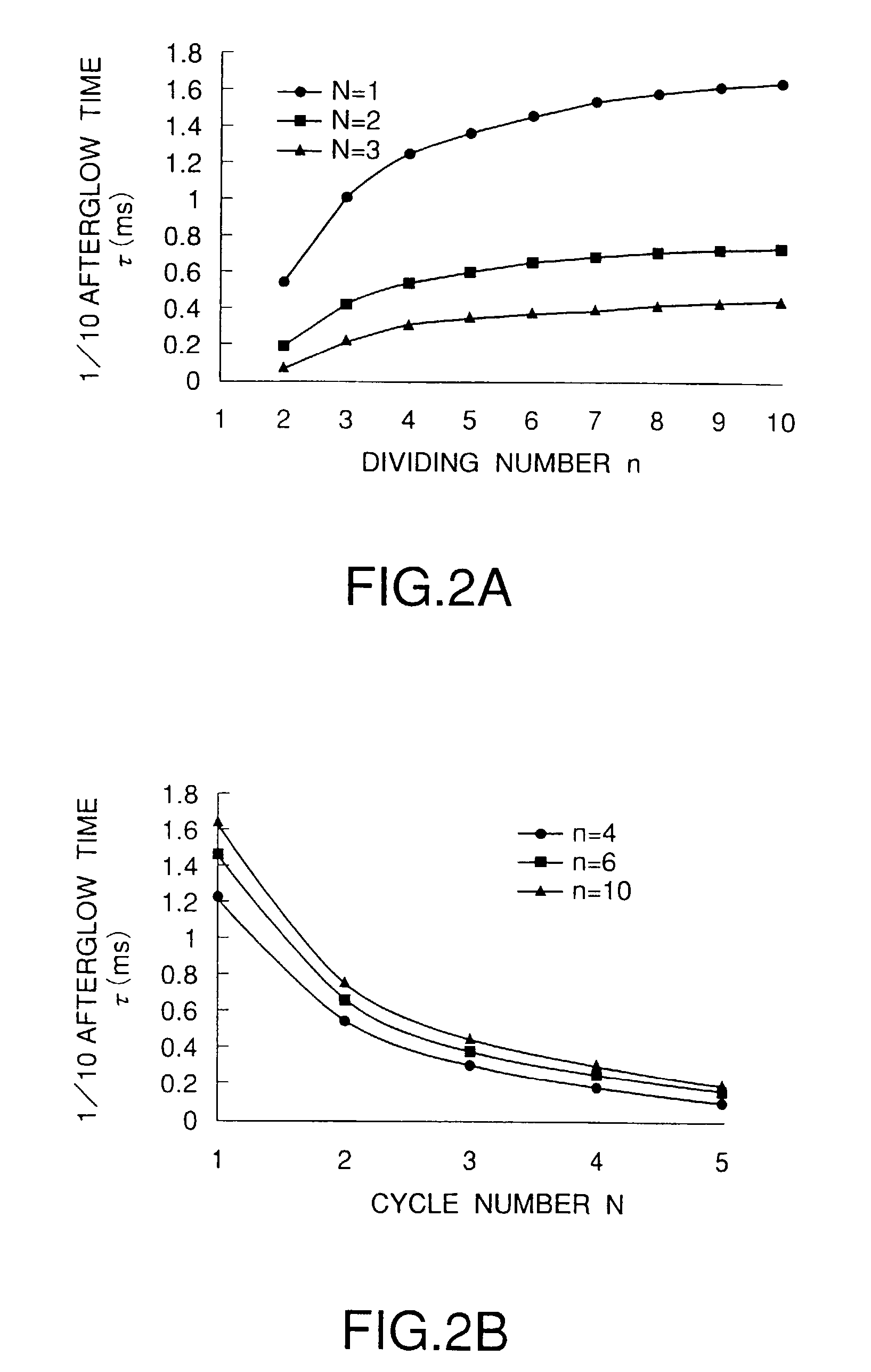
[0018]Moreover, the processing speed may increase as the variation of the frequency N for repeating the display for the three primary colors according to the second or sixth aspect. It is possible to achieve triple speed when N=1, sixfold speed when N=2, and ninefold speed when N=3 in comparison with a field frequency in a time sharing display.

Problems solved by technology

On the other hand, in the case of the time sharing display, there is caused a so-called “color breakup” interference wherein the profile of a display image appears to be iridescent due to observer's blink, the movement of observer's eye, the movement of an object on a dynamic image, and so forth.
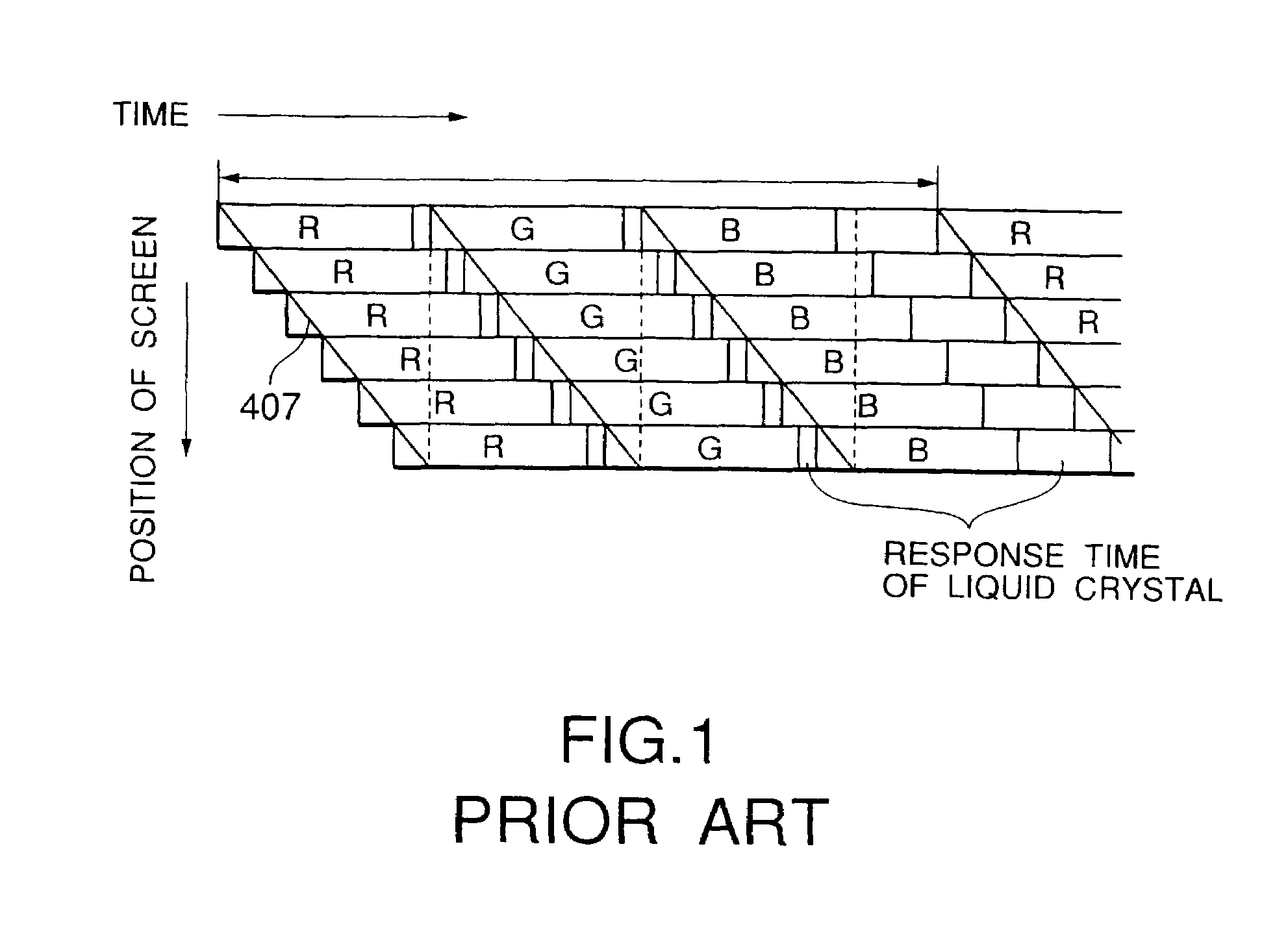
However, if the frequency of subfields R, G and B displays in one field period is intended to increase in order to more reduce the color breakup interference, the response speed of the PI cell is not sufficient as shown in FIG. 1, so that it is required to provide a switching element having a higher response time.
As described above, in the case of the conventional time sharing type display system using the liquid crystal color shutter, there are problems in that the cell itself of the liquid crystal color shutter does not have a sufficient response time, so that a color breakup interference is caused.

Method used


Image

  • Image display system and image display methods
  • Image display system and image display methods
  • Image display system and image display methods

Examples


Embodiment Construction

[0034]Referring now to the accompanying drawings, the preferred embodiments of an image display system and an image display method according to the present invention will be described below. Before describing the preferred embodiments referring to the accompanying drawings, the basic concept of the present invention will be described.

[0035]In an image display system and an image display method according to the present invention, means for time-divisionally displaying monochrome images may include all monochrome luminescent display elements for displaying monochrome images using the line scanning, such as white light emission monochrome CRTs, monochrome EL emission display elements, FEDs and plasma display elements.

[0036]According to the present invention, color display means comprises at least two liquid crystal cells having a liquid crystal of spontaneous polarization, such as ferroelectric and antiferroelectric liquid crystals, and a liquid crystal color shutter of chromatic color...


PUM


Abstract

An image display system produces a color image by arranging a color shutter capable of time-divisionally switching a plurality of colors to be displayed, in front of a monochrome image display. This image display system comprises: a self-luminous image display part for time-divisionally displaying monochrome images corresponding to three primary colors; and a color display part for time-divisionally coloring and outputting the monochrome images which formed on the side of the light outgoing surface of the self-luminous image display part and which correspond to the three primary colors. The color display part further comprises: a liquid crystal cell driven by carrying out an optical switching on the basis of the inversion between positive and negative polarities; a transparent electrode formed by dividing the liquid crystal cell into a plurality of parts; and a liquid crystal color shutter capable of optionally setting display colors for a plurality of display regions by means of the transparent electrode, the liquid crystal color shutter displaying different display colors for at least two display regions in an optional time in a driving condition.

Description

BACKGROUND OF THE INVENTION[0001]The present invention relates generally to an image display system for producing a color image by arranging a color shutter capable of time-divisionally switching a plurality of colors to be displayed, in front of a monochrome image display, and an image display method using the image display system.[0002]As a method for displaying a color image, it is usually well carried out to synthesize images of red (R), green (G) and blue (B), which are three primary colors of light, or to divide the images. Such an image synthesizing method for displaying images is divided into a space sharing display for two-dimensionally arranging dots for R, G and B to spatially arrange an image, and a time sharing display for displaying R, G and B images in time series. Typically, color cathode ray tubes and liquid crystal displays use the space sharing display since R, B and G pixels are two-dimensionally arranged. Similarly, in the case of an image pickup, there are adop...

Claims


Application Information

Patent Timeline
IPC IPC(8): G09G3/36G02F1/1335G02F1/133G02F1/1347G09G5/02H04N9/22
CPCH04N9/22G09G5/02G02F1/13473G09G2310/0235
Inventor TAIRA, KAZUKISAISHU, TATSUOSUZUKI, KOUHEIMURATA, HIROTAKANISHIMURA, TAKASHITAMATANI, MASAAKI
Owner KK TOSHIBA
Learn More