
Multipath resistant microwave moisture sensor

a multi-path resistant, moisture sensor technology, applied in direction finders using radio waves, instruments, weighing by absorbing components, etc., can solve the problems of inability to accurately control the system with resistive sensors, inability to accurately measure the moisture content, and prohibitively expensive manufacturing

Inactive Publication Date: 2006-07-18
US SEC AGRI
View PDF11 Cites 25 Cited by
  • Summary
  • Abstract
  • Description
  • Claims
  • Application Information

AI Technical Summary

Benefits of technology

[0027]Other objects and advantages of the invention will become readily apparent from the ensuing description.

Problems solved by technology

Unfortunately, the cotton processed by such machines varies widely in moisture content and to date the technology available to measure the moisture content is limited to inaccurate low cost resistance moisture sensors or extremely expensive microwave moisture sensors.
Another disadvantage to this technique is the need for pressing the cotton against a resistance sensing plate, as this restricts the possible locations where this technique can be applied in a cotton gin in addition to the very likely possibility of stoppage / blockage of the cotton flow due to system malfunctions.
As such, currently there are no resistive sensors that can be accurately used to control these systems as the surface moisture these systems add to the cotton alter the calibration of these sensors in an uncontrolled manner.
The only other types of sensors that can be utilized are very expensive microwave bale moisture sensors that are typically utilizing very high frequency microwave technology that is prohibitively expensive to manufacture.
Unfortunately, when moisture is added to the bale in an excessive amount, this grade has been shown to change as the moisture degrades the cotton.
This has led to hundreds of bales being returned back to the gins and has caused a great deal of concern in the industry over the potential damage to the USDA-AMS classing grade.
This system utilizes a near-field electric field measurement which to date has demonstrated poor repeatability, low accuracy and severe drift over time problems.
As such, all of these patents provide very expensive solutions.
Additionally it should be noted that the radar cross-section of the typical metal bale ties is very large at these high microwave frequencies and has been shown to cause significant signal interference at these very high frequencies, thereby rendering all of these frequencies unusable for use in moisture measurement of metal tied cotton bales.
When utilizing microwave and radio frequency based sensors in such buildings, standing waves are setup that cause significant interference with the measurement.
This interference degrades the accuracy of these systems and in most situations renders the technique unusable and makes it impossible to calibrate the system ahead of time at the factory.
Thus, the units are shipped uncalibrated and must be installed with expensive and elaborate field calibration techniques that add significant cost to the system as the manufacturer must pass on this added cost of doing business.

Method used


Image

  • Multipath resistant microwave moisture sensor
  • Multipath resistant microwave moisture sensor
  • Multipath resistant microwave moisture sensor

Examples


example 1

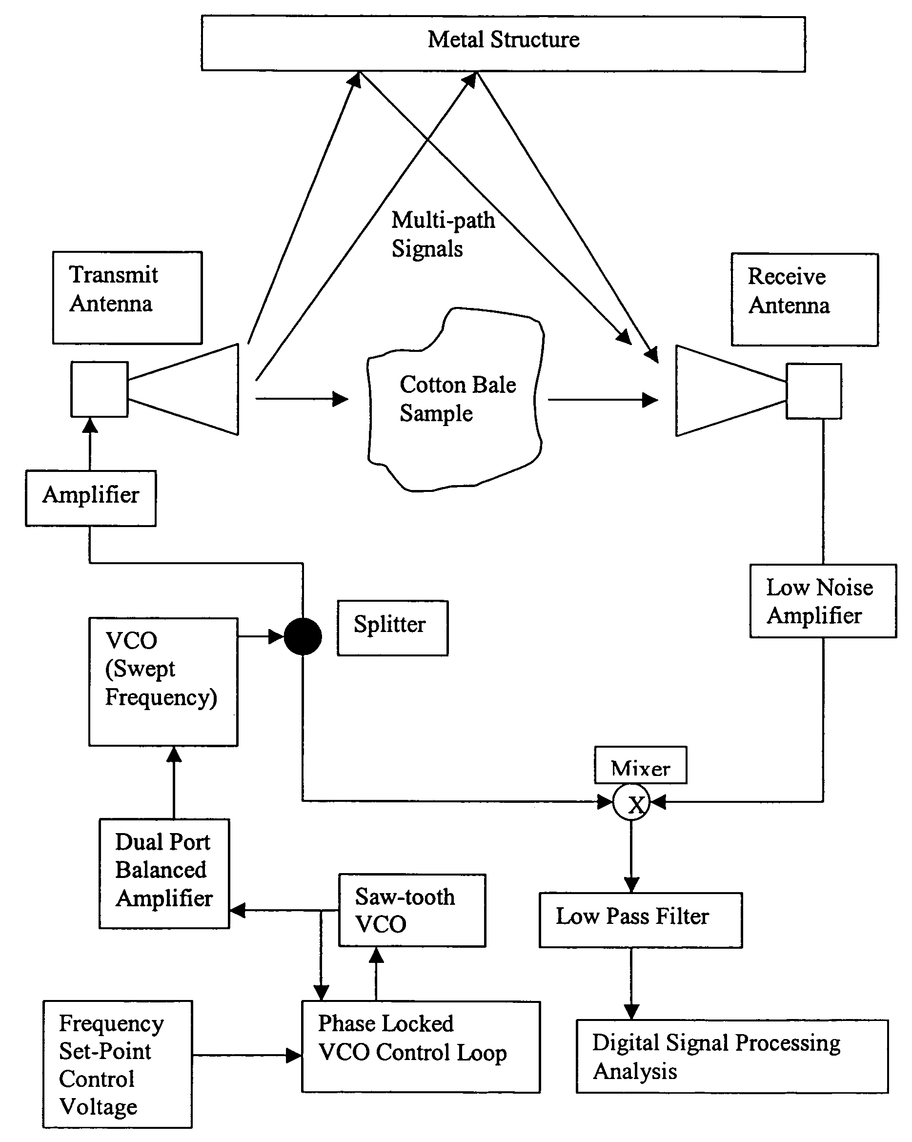
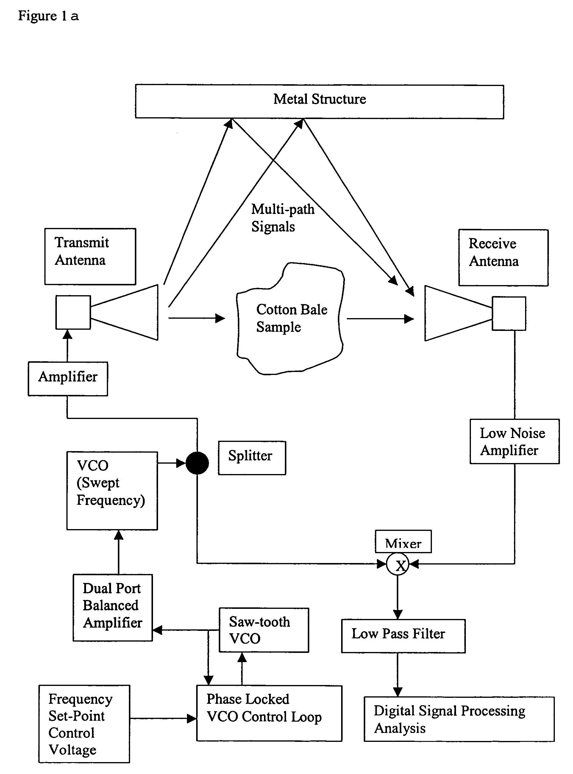
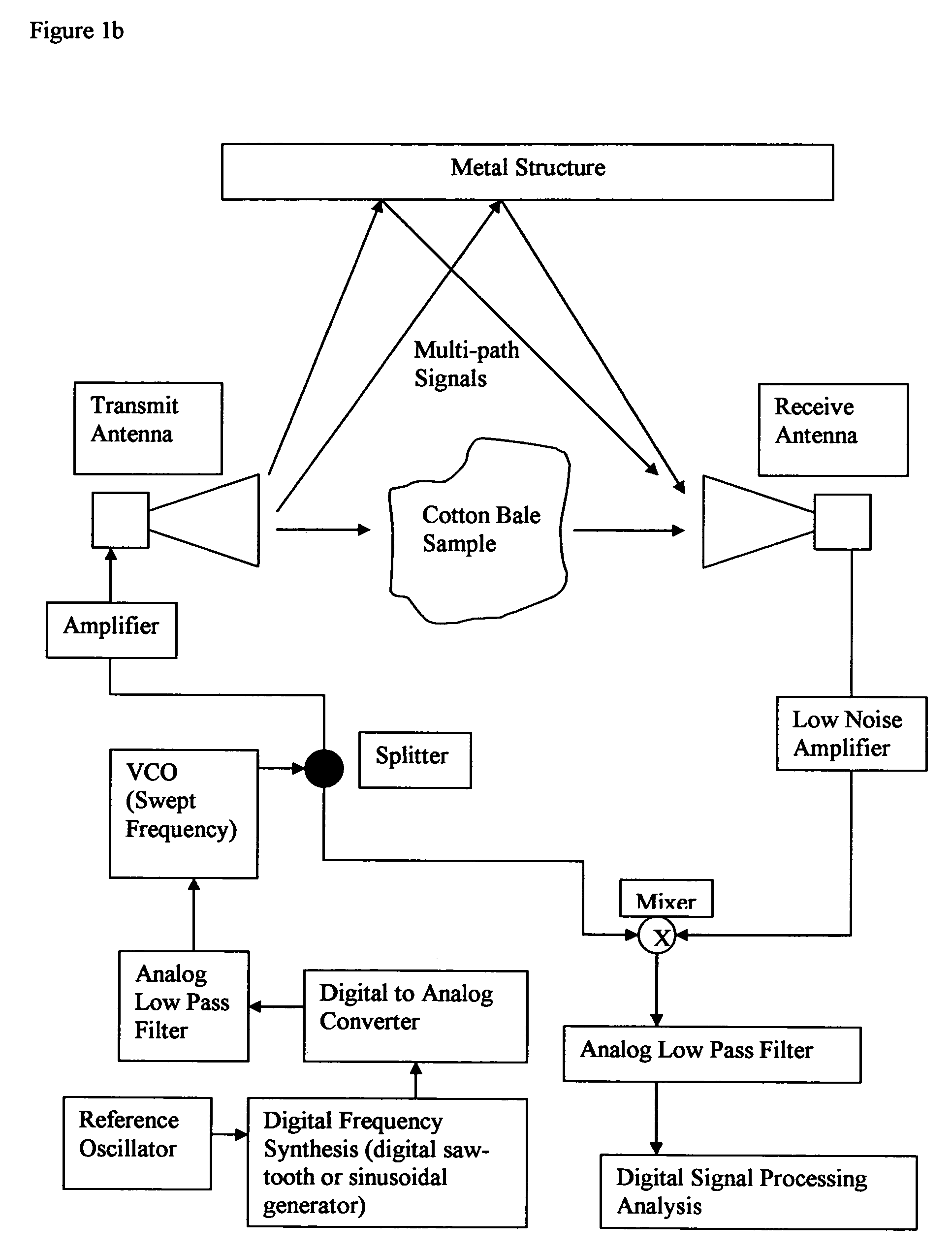
[0086]The apparatus of the above-described first embodiment and shown in FIG. 1 was used to measure the moisture of baled cotton. This technique was analyzed with the multi-path interference modeled by a set of three delayed signals that was added at the receiving antenna to the received signal. The delayed multi-path signals consisted of a 3, 5, 7 and 20 m signal delay. This delay is due to the signal propagating out into multiple directions with each of these separate signal vectors following a longer path to the receiving antenna as discussed earlier. As is standard in the telecommunications industry, the signal strength of the interference can be reduced in signal strength to a fraction of the transmitted signal (Stremler, ibid). Typical values used in this type of modeling suggest levels of less than 10%, however in this case it was felt that a 100% signal strength level would be a better indication of success as the distances involved are very small and there is no real attenu...

example 2

[0090]A preferred apparatus was constructed for measuring the moisture of cotton bales. This system assumes a cotton bale density such that an industry standard Universal Density bale (UD bale weighs approximately 500 lbs, and a path length of the material of 21 inches (the short dimension of the UD bale through which the signals will be transmitted.

[0091]The following steps were performed two times; once with no material between the antennas (air-instrument propagation delay measurement) and again with the cotton bale or material under test located between the two antennas (material plus air-instrument measured propagation delay). After obtaining both the air propagation delay and the material plus air-instrument propagation delay the final measurement is the difference between these two readings after correction for the rate of frequency deviation. It is this final measurement that provides a measure of the permittivity of the material as well as the moisture content of the materi...


PUM


Abstract

The moisture content of a test material may be determined using a microwave-based process and device which is free from interference by multipath standing waves. Multipath signals may be electronically removed from the measured signal.

Description

BACKGROUND OF THE INVENTION[0001]1. Field of the Invention[0002]The invention relates to an improved microwave system for measuring the moisture content of cotton bales and other materials.[0003]2. Description of the Prior Art[0004]Modern cotton gins have the purpose of extracting lint (the cotton) from trash and seeds—usually the sticks, leaves and burrs that are entrained with the cotton. These modern gins include many individual machine components that are operated sequentially to form the gin processing line. The components are often specific in the types of trash that they remove. Stick machines, inclined cleaners, and especially lint cleaners process the lint to a purity where it can be baled and delivered to spinning mills. Included in these systems are drying systems as it is imperative that the cotton must be within a range of moisture contents in order for the machinery to work properly.[0005]Unfortunately, the cotton processed by such machines varies widely in moisture co...

Claims


Application Information

Patent Timeline
Patent Type & Authority Patents(United States)
IPC IPC(8): G01R27/04
CPCG01N22/04G01N33/46G01N33/36
Inventor PELLETIER, MATHEW G.
Owner US SEC AGRI
Learn More