
Cable guide sleeving structure

a sleeving structure and cable guide technology, applied in the direction of insulated conductors, cables, instruments, etc., can solve the problems of difficult installation of lines within existing ductwork, difficult positioning of additional cables, and inability to use them for additional cables, etc., to facilitate the drawing of the sleeving structure through the du

Inactive Publication Date: 2006-07-18
WESCO DISTRIBUTION
View PDF47 Cites 48 Cited by
  • Summary
  • Abstract
  • Description
  • Claims
  • Application Information

AI Technical Summary

Benefits of technology

[0014]To facilitate drawing the sleeving structure through a duct, an attachment piece engages an end of the sleeve. The attachment piece is adapted to receive a line for drawing the sleeve through the outer duct. Preferably the attachment piece is adapted to attach the sleeve to a plurality of other sleeves as well when the sleeves are arranged in overlying relation with one another, thus enabling a plurality of sleeves to be drawn through the duct simultaneously.

Problems solved by technology

Once the duct is in place, for example, underground or throughout a building structure, it is difficult to position additional cables within it, for example, to increase the capacity of the communication network or replace a failed cable.
The relative inaccessibility of the duct work often precludes any attempt to use it for additional cables.
Installation of the lines within existing duct work is often a difficult task since the duct work typically does not follow a straight path, but winds its way throughout the building structure.
The insulation used with electrically conducting wire and the sheathing for optical fibers typically do not meet the requirements of the Plenum Rating Standard.

Method used


Image

  • Cable guide sleeving structure
  • Cable guide sleeving structure
  • Cable guide sleeving structure

Examples


Embodiment Construction

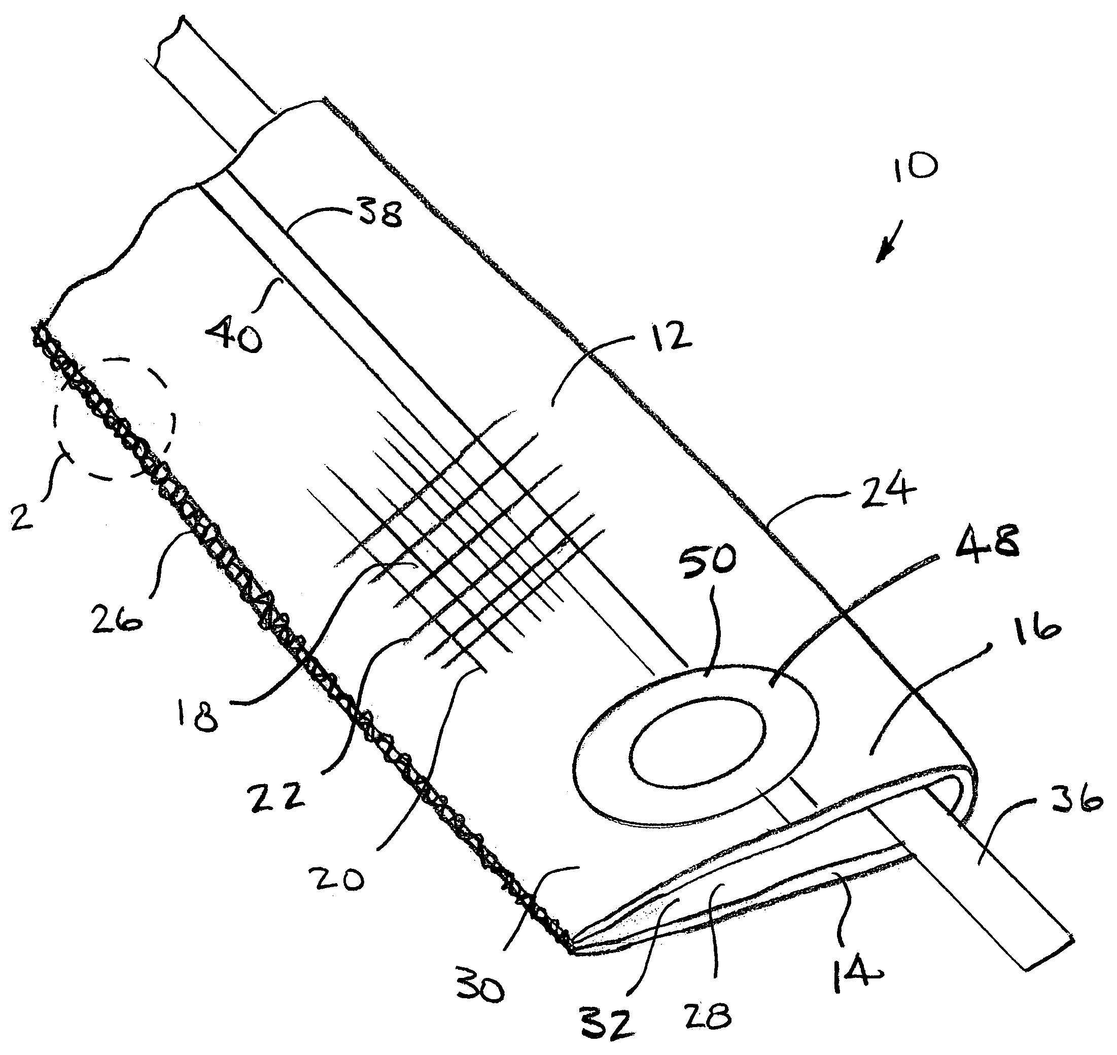
[0032]FIG. 1 shows an elongated sleeve structure 10 according to the invention. Sleeve structure 10 comprises a flexible sleeve 12 comprising opposed layers 14 and 16 of woven resilient filaments 18. Filaments 18 comprise warp yarns 20 and fill yarns 22, the fill yarns being common to both layers 14 and 16. The opposed layers 14 and 16 have a common seamless edge 24 and are joined to one another along a second edge 26 formed, as best shown in detail in FIG. 2, by interlooping successive traverses of the fill yarn 22 with one another. In some cases, depending upon the mode of manufacture, a binder yarn 23 is used to facilitate closure of the second edge 26. The binder yarn 23 traverses lengthwise along the edge and loops around pairs of fill yarn loops 22. Preferably, as shown in FIG. 1, the opposed layers 14 and 16 are of equal width and comprise sidewall portions 28 and 30 surrounding and defining a central space 32. The opposed layers 14 and 16 are nominally in a substantially fla...


PUM

PropertyMeasurementUnit
diameteraaaaaaaaaa
diameteraaaaaaaaaa

Abstract

An elongated sleeve structure for insertion and protection of elongated items within a duct is disclosed. The sleeve structure is formed from a flexible sleeve woven from warp and fill yarns to produce opposed layers in closely spaced relation. The layers have a common seamless edge and are joined along a second edge by a knit stitch formed by interlooping of successive traverses of the fill yarn which is common to both layers. The layers are of equal width and are resiliently separable into a spaced apart relationship defining a central space which accommodates the elongated items. A pull tape is positioned between the opposed layers for drawing the elongated items through the sleeve central space once the sleeve structure is positioned within the duct. Multiple sleeve structures may be joined together in an assembly using an attachment piece allowing a plurality of sleeve structures to be pulled simultaneously.

Description

RELATED APPLICATIONS[0001]This application is based on and claims priority to U.S. Provisional Application No. 60 / 406,607, filed Aug. 28, 2002 and U.S. Provisional Application No. 60 / 476,939, filed Jun. 9, 2003.FIELD OF THE INVENTION[0002]This invention relates to sleeving and sleeving assemblies for encasing and protecting elongated items and especially to lengths of sleeving which may be drawn through in situ duct work for later facilitating positioning of elongated items in the duct work.BACKGROUND OF THE INVENTION[0003]Elongated items such as wiring bundles or optical fiber cables used for telephone, video or computer communication networks are often installed in protective ducts which may be buried underground, strung from support stanchions or positioned within building structures along with other utility and service lines. Such ducts may be, for example, extruded polymer tubes which provide substantially continuous protection to the elongated items from moisture, abrasion, im...

Claims


Application Information

Patent Timeline
Patent Type & Authority Patents(United States)
IPC IPC(8): H01B11/06D03D1/00D03D15/56F16L3/26F16L7/00F16L57/00G02B6/44H02G1/06H02G1/08H02G3/04
CPCF16L3/26F16L7/00F16L57/00H02G3/0487G02B6/4459G02B6/4463H02G3/0481F16L57/04D03D1/0043G02B6/50H01B7/29
Inventor GLADFELTER, HARRY F.MATTE, PAUL J.PENDERGAST, PATRICK M.ROSS, DAWN D.
Owner WESCO DISTRIBUTION
Learn More