
Spark ignition internal combustion engine

a technology of internal combustion engine and spark ignition, which is applied in the direction of machines/engines, electric control, instruments, etc., can solve the problems of poor ignitability of low-octane fuels, poor antiknock properties, poor ignitability of high-octane fuels, etc., and achieve good prediction of mixing proportions. , the effect of good prediction

Inactive Publication Date: 2006-07-18
TOYOTA JIDOSHA KK
View PDF22 Cites 24 Cited by
  • Summary
  • Abstract
  • Description
  • Claims
  • Application Information

AI Technical Summary

Benefits of technology

This solution enables precise estimation and adjustment of fuel mixing proportions, improving engine efficiency, reducing knocking, and enhancing fuel economy by accurately setting the octane number and ignition timing based on real-time measurements and operation states.

Problems solved by technology

Low-octane fuels are good in ignitability but poor in antiknock property, whereas high-octane fuels are poor in ignitability but good in antiknock property.
According to the existing technologies, there is no method for detecting this deviation in octane number.
Therefore, if the octane number deviates, the engine is operated with the deviated octane number remaining, and therefore cannot exactly deliver intended operation performance, that is, intended accelerating performance, intended fuel consumption, and intended exhaust emissions.
However, the apparatus described in Japanese Patent Application Laid-Open Publication No. 4-234571 merely performs a generally-termed symptomatic treatment in which a deviation in the octane number of fuel is met by adjustment in the ignition timing, and does not provide a radical cure in which the octane number of fuel is set to a predetermined value.
That is, since the mixing proportion is not determined, the apparatus is not able to eliminate deviation in the mixing proportion.
In the case of a large deviation in the mixing proportion, the apparatus may be incapable of achieving a practical effect.

Method used


Image

  • Spark ignition internal combustion engine
  • Spark ignition internal combustion engine
  • Spark ignition internal combustion engine

Examples


first embodiment

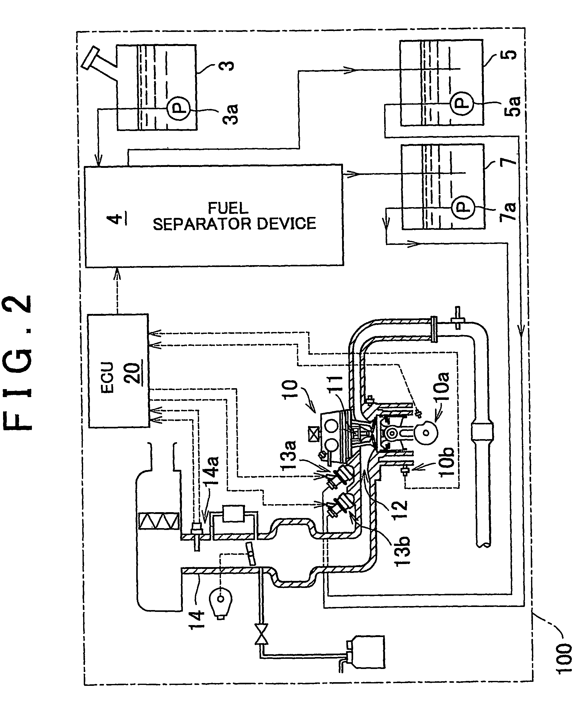
[0042]Preferred embodiments of the invention will be described hereinafter with reference to the accompanying drawings. FIG. 1 is a schematic diagram illustrating a construction of a Referring to FIG. 1, a low-octane fuel tank 5 of a vehicle 100 stores a low-octane fuel that has a relatively low octane number, and a high-octane fuel tank 7 stores a high-octane fuel that has a relatively high octane number.

[0043]The low-octane fuel and the high-octane fuel are supplied to fuel injection valves 13a, 13b via a low-octane fuel pump 5a and a high-octane fuel pump 7a, respectively. The two fuel injection valves 13a, 13b are attached to an intake port 12 of a spark ignition internal combustion engine (hereinafter, simply referred to as “engine”) that has an ignition plug 11. The fuel injection valves 13a, 13b inject into the intake port 12 the low-octane fuel and the high-octane fuel at predetermined proportions suitable for the operating condition in accordance with a command from an ele...

second embodiment

[0059]A second embodiment will next be described.

[0060]FIG. 4 is a flowchart illustrating a control of a second embodiment as a first modification of the first embodiment. Steps 101 to 112 are the same as those in the first embodiment. The second embodiment is different from the first embodiment in that step 113 is added, in which the retardation in timing caused by the knock control is removed.

[0061]FIG. 18 illustrates concept and effect of a control of the second embodiment. As indicated in FIG. 18, if knocking occurs, the ignition timing is retarded by the knock control. However, the high-octane fuel proportion RHRON is increased, so that occurrence of knocking becomes unlikely and therefore the ignition timing is returned to the original timing. Hence, the fuel consumption reduces (the fuel efficiency improves), and deterioration in fuel economy can be prevented.

[0062]A third embodiment will next be described. FIG. 5 is a flowchart illustrating a control in accordance with the t...

third embodiment

[0064]FIG. 19 illustrates concept and effect of the control of the As indicated in FIG. 19, if knocking does not occur, the ignition timing is advanced to MBT, so that the fuel consumption reduces (the fuel efficiency improves) and the fuel economy improves. If the basic ignition timing SA is set at the MBT, there is no effect achieved. However, if the basic ignition timing SA is set at a retarded side of the MBT in order to prevent occurrence of knocking, the ignition timing can be advanced to the MBT. Therefore, the aforementioned effect can be achieved.

[0065]Next, a fourth embodiment will be described. FIG. 6 is a flowchart illustrating a control in accordance with the fourth embodiment. Steps 101 to 113 are the same as those in the second embodiment. However, the fourth embodiment is different from the second embodiment in that step 114a is added. In step 114a, the low-octane fuel proportion is increased if a negative determination is made in step 102, that is, if knocking does...


PUM


Abstract

A low-octane fuel and a high-octane fuel stored in a low-octane fuel tank (5) and a high-octane fuel tank (7), both having known octane numbers, are injected from fuel injection valves (13a, 13b) into an intake port (12) at a mixing proportion that achieves a standard octane number set in accordance with the engine operation state. If knocking occurs during a predetermined steady engine operation state, the knocking is detected by a knock sensor (10b) and, corresponding to the knocking, the ignition timing is retarded from a basic ignition timing. A deviation in octane number is determined from the amount of ignition timing retardation with reference to a map, and is then corrected by the intake air pressure. On the basis of the corrected deviation in octane number, a deviation in the mixing proportion of the high-octane fuel is determined with reference to a map. The thus-determined deviation is added to a target mixing proportion computed corresponding to the standard octane number, thereby computing the present mixing proportion.

Description

BACKGROUND OF THE INVENTION[0001]1. Field of the Invention[0002]The invention relates to a spark ignition internal combustion engine in which a high-octane fuel and a low-octane fuel are mixed by a fuel mixture means adapted for mixing high and low-octane fuels at variable mixing ratios and a mixed fuel is supplied into a combustion chamber.[0003]2. Description of the Related Art[0004]Low-octane fuels are good in ignitability but poor in antiknock property, whereas high-octane fuels are poor in ignitability but good in antiknock property. Internal combustion engines in which a low-octane fuel and a high-octane fuel are mixed and supplied to an engine by fuel injection valves so as to meet an operating condition of the engine are known, as described in Japanese Patent Application Laid-Open Publication No. 2001-050070.[0005]In such an internal combustion engine, however, the octane number of a mixed fuel supplied into the combustion chamber sometimes deviates from a target octane numb...

Claims


Application Information

Patent Timeline
Patent Type & Authority Patents(United States)
IPC IPC(8): F02P5/152G06F17/00F02D19/08F02D41/00F02D45/00F02P5/153
CPCF02D19/081F02D35/027F02D41/0025F02P5/1527F02D19/0649F02D19/0665F02D19/0671F02D19/0692F02D2200/0612Y02T10/36Y02T10/46Y02T10/30Y02T10/40
Inventor ODA, TOMIHISANIIMI, KUNIAKI
Owner TOYOTA JIDOSHA KK
Learn More