
Programmable delay method for hierarchical signal balancing

a hierarchical signal and delay technology, applied in the field of signal balancing in integrated circuits, can solve the problems of signal to be rebalanced, complicated rlm reuse between individual designs, increased turn around time (tat), etc., and achieve the effect of reducing manual design efforts and reducing turn-around tim

Inactive Publication Date: 2006-07-04
TWITTER INC
View PDF17 Cites 7 Cited by
  • Summary
  • Abstract
  • Description
  • Claims
  • Application Information

AI Technical Summary

Benefits of technology

"This patent describes a method for automatically balancing signals across multiple circuit designs. This reduces the need for manual adjustments and saves time. The method uses programmable delay elements that can be adjusted to match signal latency requirements in each design. The delay elements are fixed after fabrication, so they cannot be re-programmed. The method has several advantages, including independence between different circuit designs, automatic adjustment of signal latency, and tight skew within a single circuit design. It also supports circuit designs with varying numbers of buffer levels. Overall, this method simplifies the design process and improves the efficiency of signal balancing."

Problems solved by technology

1) Adding the proper amount of delay buffers and adjusting wire delays greatly increases Turn Around Time (TAT);
2) When designing signal paths within each RLM, consideration must be taken to match other RLM's latencies;
3) RLM reuse between individual designs is complicated;
4) Any modification to a RLM or the top level of a design effects the entire signal path, possibly requiring the signal to be rebalanced, wasting previous manual efforts; and
5) Re-balancing a hierarchical clock tree involves discarding previous manual efforts and restarting adjustments.
Large variations in RLM size / load count result in large signal latency variations within RLMs.
Of course, this approach has the attendant problems relating to having to design-in additional logic that would otherwise be unnecessary.

Method used


Image

  • Programmable delay method for hierarchical signal balancing
  • Programmable delay method for hierarchical signal balancing
  • Programmable delay method for hierarchical signal balancing

Examples


Embodiment Construction

[0025]Traditionally signal balancing in hierarchical designs is performed by one of two main approaches:

[0026]1) Designing each RLM to have a single common signal latency.

[0027]There are two primary drawbacks to designing / planning RLMs to have a common signal latency. First, achieving a specific latency target is difficult and typically requires extensive manual effort increasing design turnaround time. Second, RLM reuse is complicated since every design has varying signal latency requirements.

[0028]2) Flattening (i.e. removing all hierarchy) from the design in order to process a balanced signal as a regular design.

[0029]Loses all the advantages of the hierarchical design approach including allowing several designers to process separate design components in parallel. The software speed up of processing smaller design segments at a single time is lost. In addition, tight intra-RLM skew is reduced which is one of the most important characteristics of a hierarchical signal.

[0030]In thi...


PUM


Abstract

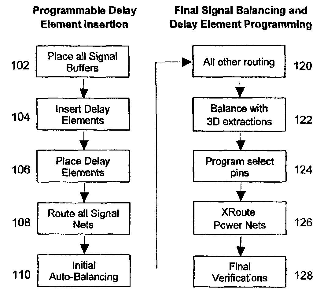
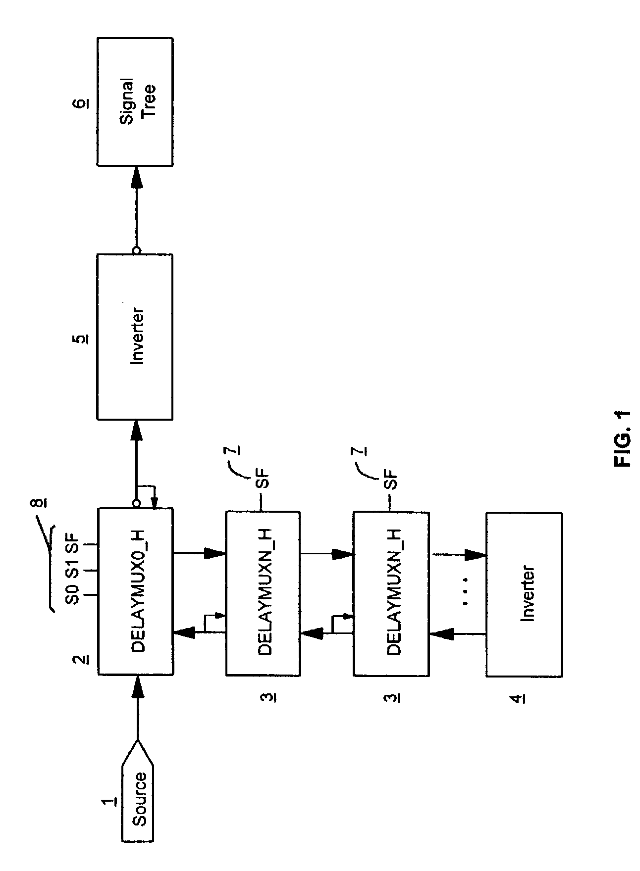
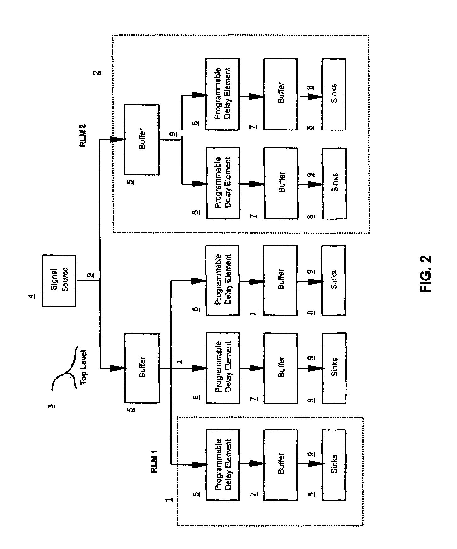
A method for signal balancing across multiple random logic macros. The method inserts a programmable delay element into the design before the last buffer level on all signal paths. The random logic macro is then fully designed including cell placement and wiring. With programmable delay buffers in place, the random logic macros may be used within multiple designs, each having varying signal latency requirements.

Description

BACKGROUND OF THE INVENTION[0001]1. Field of the Invention[0002]This invention relates to signal balancing in integrated circuits. More particularly it relates to signal balancing in system on chip integrated circuits. More specifically, it applies to balancing signal arrival time in IC designs between multiple random logic macros (RLM).[0003]2. Background of the Invention[0004]Currently, in order to balance signal arrival times between multiple RLMs, designers manually add buffers and make wiring adjustments by hand to adjust the signal's latency both within each RLM and at the top level of a design. Such a method is undesirable for the following reasons:[0005]1) Adding the proper amount of delay buffers and adjusting wire delays greatly increases Turn Around Time (TAT);[0006]2) When designing signal paths within each RLM, consideration must be taken to match other RLM's latencies;[0007]3) RLM reuse between individual designs is complicated;[0008]4) Any modification to a RLM or the...

Claims


Application Information

Patent Timeline
Patent Type & Authority Patents(United States)
IPC IPC(8): G06F17/50
CPCG06F17/505G06F30/327
Inventor FRY, THOMAS W.MENARD, DANIEL R.NORMAND, PHILLIP PAUL
Owner TWITTER INC
Learn More