Wavelength-selective 1xN2 switches with two-dimensional input/output fiber arrays
a technology of input/output fiber array and wavelength selectivity, which is applied in the field of wavelength selectivity switches, can solve the problems of limited port count and limited input/output fiber maximum number, and achieve the effect of reducing the number of input/output fibers and limiting the maximum number of optical input/output fibers
- Summary
- Abstract
- Description
- Claims
- Application Information
AI Technical Summary
Benefits of technology
Problems solved by technology
Method used
Image
Examples
example 1
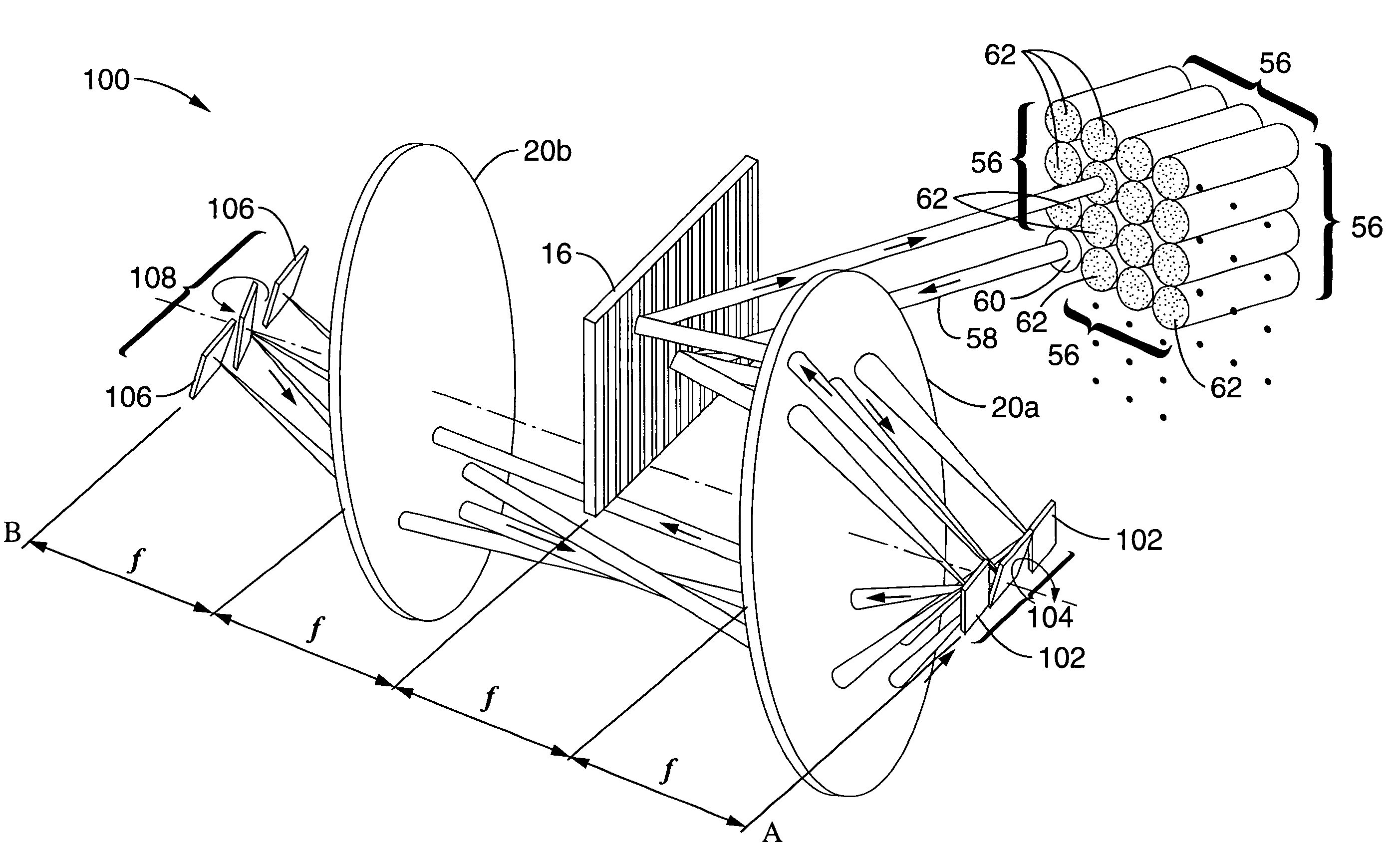
[0030]A prototype system according to the embodiment shown in FIG. 3 through FIG. 5 was constructed using lenses with 15-cm focal lengths. A channel spacing of 75 GHz was attained with an 1100 grooves / mm grating. The number of wavelength channels was 15, which was limited only by the number of mirrors in the array that could be accommodated on our particular chip. The optical system supported a 3×3 fiber collimator array at the input plane, which was used as a 1×8 wavelength-selective switch with an input collimator located at the center of the array. Discrete collimators were used to simulate the 2D array. The focused beam waist on the micromirror was 30 μm. With a micromirror pitch of 160 μm, the acceptable beam waist can be as large 60 μm. Using this number, the input collimator size can be reduced by two times. Hence, the array size at the input plane can be increased to 5×5, which can be used for a 1×24 wavelength-selective switch. The fiber-to-fiber insertion loss of the syste...
example 2
[0031]A prototype system according to the embodiment shown in FIG. 3 through FIG. 5 was constructed using 1×30 arrays of surface-micromachined analog micromirrors with orthogonal scanning directions. The system was configured with a 50 GHz channel spacing using an 1100 grooves / mm grating. The optical insertion loss was measured to be 12.5 dB, and the extinction ratio was measured to be 36 dB. The switching time was found to be less than 1 msec. Discrete commercial collimators with 2.5 mm beam waist were used due to their availability. If a 2D collimator array is used, a maximum of 4×10=40 spatial channels can be accommodated for the current optical design.
[0032]As discussed above, discrete collimators can be used in the embodiments of the invention heretofore described. The examples set forth above relied on the use of discrete collimators to simulate a 2D collimator array. However, the large housings of discrete collimators tend to reduce the practical port count, and the alignment...
example 3
[0033]A prototype system was constructed according to the embodiment shown in FIG. 6. A commercial 6×6 fiber collimator array was used in this system, and the pitch of the array was 1 mm with a beam radius of 125 μm. A 6× telescope was used to expand the optical beams before they are spatially dispersed by the grating. The beam expander reduces the optical spot size on the micromirror. A 600-grooves / mm grating and two lenses with 15-cm focal length were selected for this system. In addition, 10 of the 36 (6×6) spatial channels were covered by the effective lens area the system. Therefore, the system functioned as a 1×9 WSS but the port count can be increased by improving the fill factor of the 2D collimator array. The microlens diameter-to-pitch ratio of the collimator array was relatively low (50%). The fiber-to-fiber insertion loss was measured to be 14 dB when the optical beam was coupled back to the input port. When the optical beam was switched to another spatial channel, the i...
PUM
 Abstract
Description
Claims
Application Information
 - R&D
- Intellectual Property
- Life Sciences
- Materials
- Tech Scout
- Unparalleled Data Quality
- Higher Quality Content
- 60% Fewer Hallucinations
Browse by: Latest US Patents, China's latest patents, Technical Efficacy Thesaurus, Application Domain, Technology Topic, Popular Technical Reports.
© 2025 PatSnap. All rights reserved.Legal|Privacy policy|Modern Slavery Act Transparency Statement|Sitemap|About US| Contact US: help@patsnap.com


