
Display with active contrast enhancement

a technology of contrast enhancement and display, applied in the field of displays, can solve the problems of insufficient switching speed obtainable with hunt's display, insufficient enhancement of image contrast, and insufficient to achieve desired image clarity, etc., to achieve simple enhancement of image contrast in the display, less reliability concern, and high reliability

Inactive Publication Date: 2006-07-04
CANON KK
View PDF22 Cites 61 Cited by
  • Summary
  • Abstract
  • Description
  • Claims
  • Application Information

AI Technical Summary

Benefits of technology

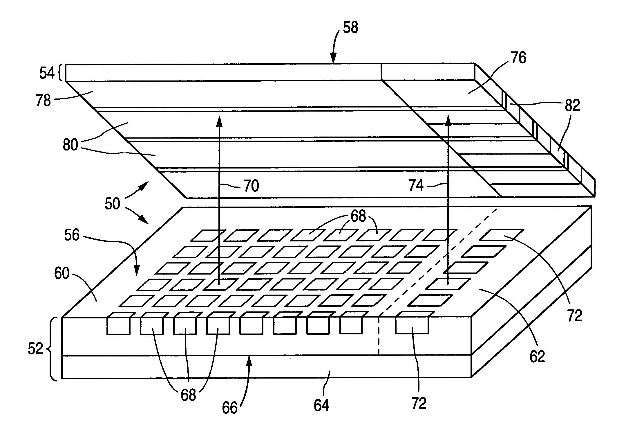
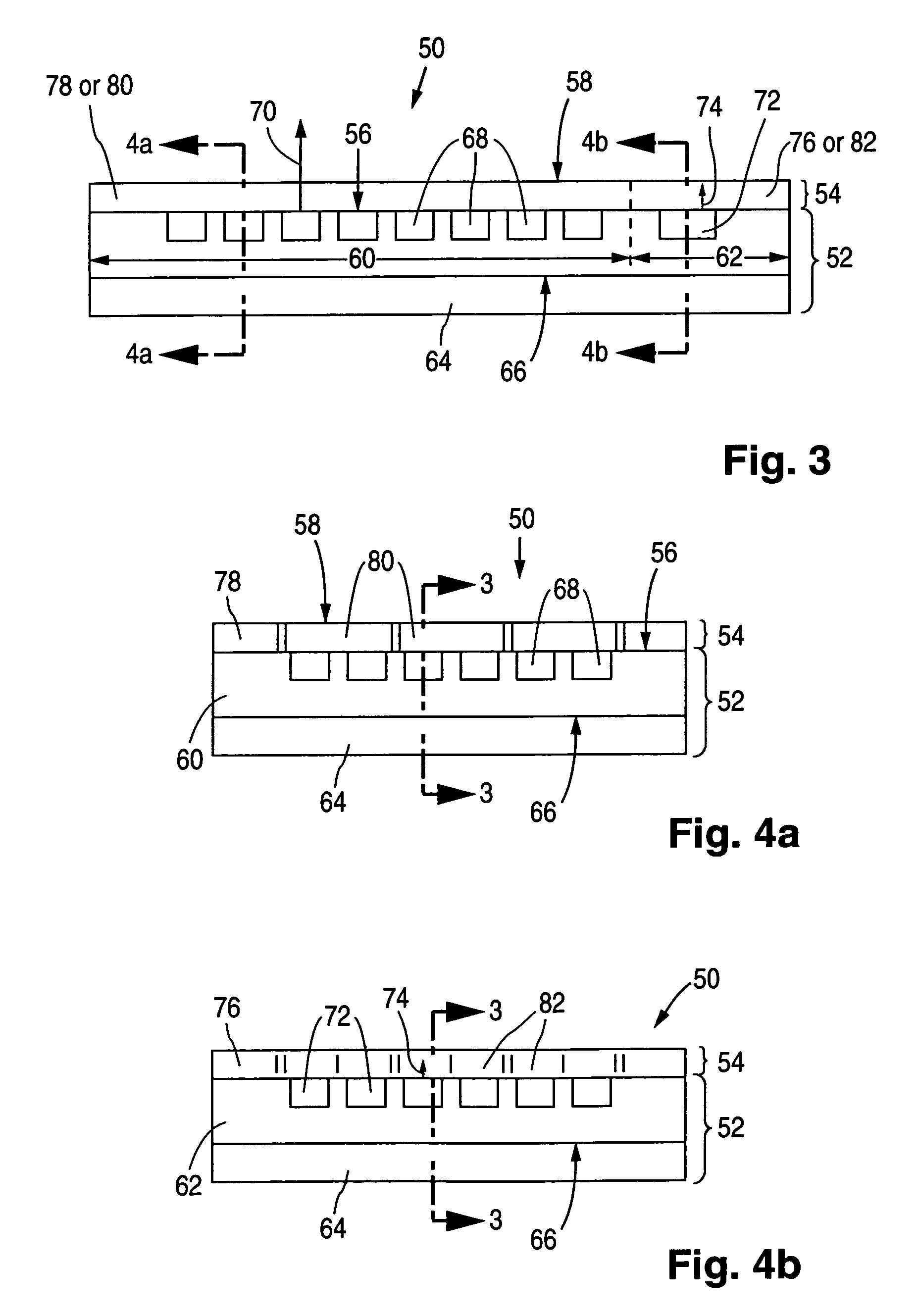
[0010]By appropriately switching the shutter strips between their light-transmissive and light-absorptive states, the image contrast is actively enhanced in the present display. In particular, the fraction of ambient light reflected from a portion of the display having a shutter strip in its absorptive state is reduced compared to what would occur if the shutter strip were absent. Hence, the overall fraction of ambient light reflected from the display's viewing area is reduced. The contrast enhancement is especially helpful in high ambient lighting conditions where the high magnitude of the ambient light might otherwise degrade the image.
[0022]In short, the present display, typically of the flat-panel type, provides active contrast enhancement suitable to make the display's image clear under conditions of high ambient light. The shutter strips can be switched rapidly between light-transmissive and light-absorptive states precisely when they need to be switched. The mechanism used to enhance the image contrast in the display is simple and highly reliable. Heat and humidity are of considerably less reliability concern than in the displays of Hunt and Koehler / Beran et al. The present display can be fabricated at low cost. Accordingly, the invention provides a large advance over the prior art.

Problems solved by technology

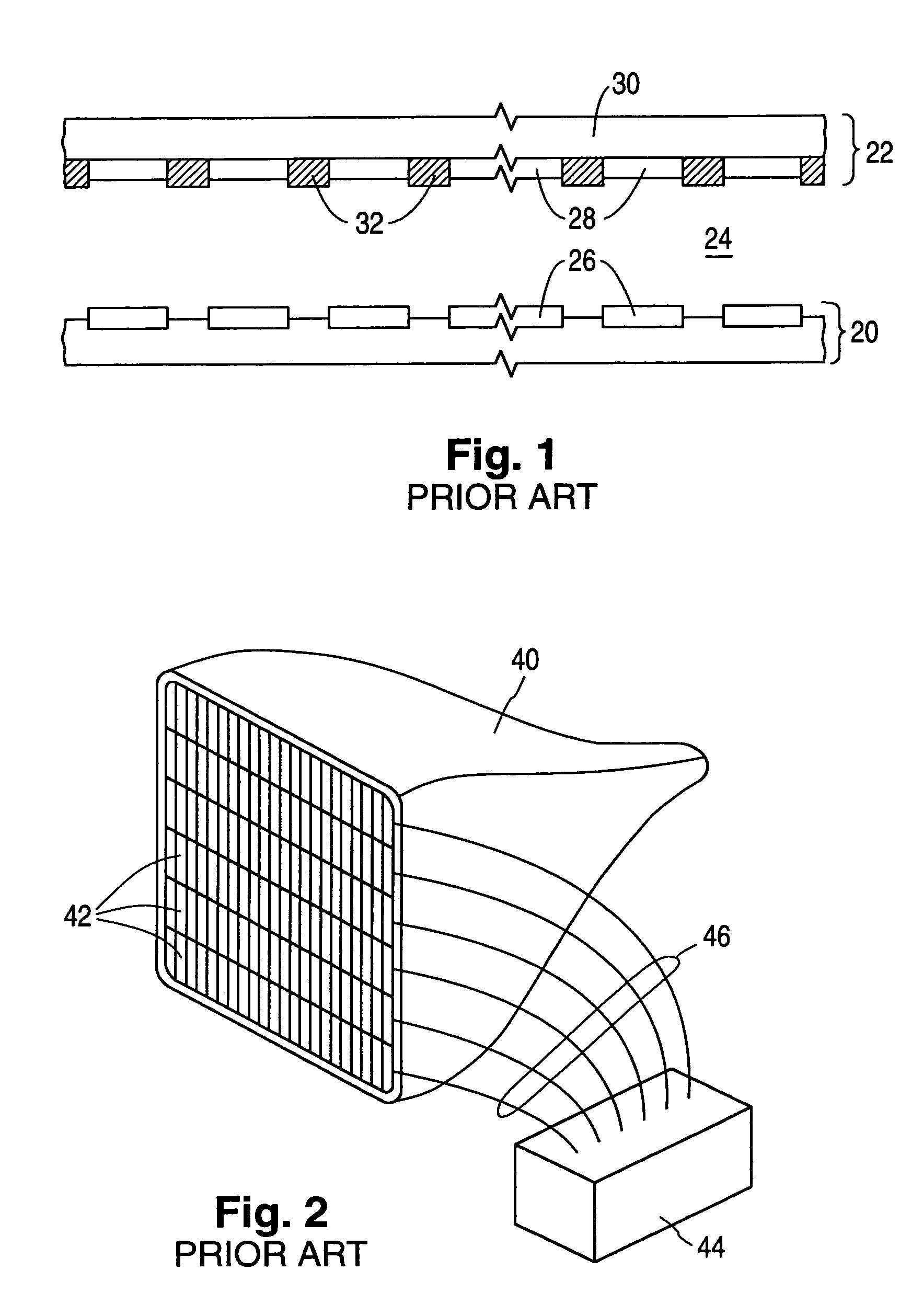
As a result, the enhanced image contrast produced by black matrix 32 is still sometimes insufficient to achieve desired image clarity, particularly when the ambient light is of high magnitude.
It is doubtful that the switching speed obtainable with Hunt's display would be great enough for many future applications.
Furthermore, the LCDs employed in Hunt and Koehler / Beran et al utilize polarizers which significantly reduce image intensity.
The polarizers may be damaged by heat and / or humidity, and thus raise reliability concerns.

Method used


Image

  • Display with active contrast enhancement
  • Display with active contrast enhancement
  • Display with active contrast enhancement

Examples


Embodiment Construction

General

[0036]Image contrast is actively enhanced in a display, normally a flat-panel display, configured according to the invention. The present flat-panel display is suitable for use as a flat-panel television or a flat-panel video monitor for a personal computer, a lap-top computer, or a workstation. The light which produces the display's image is then visible light. Alternatively, the present display can be tailored to applications in which the image is produced by light, e.g., infrared light, which lies outside the visible spectrum.

[0037]In the following description, the term “electrically insulating” (or “dielectric”) generally applies to materials having an electrical resistivity greater than 1010 ohm-cm at 25° C. The term “electrically non-insulating” thus refers to materials having an electrical resistivity of up to 1010 ohm-cm at 25° C. Electrically non-insulating materials are divided into (a) electrically conductive materials for which the electrical resistivity is less t...


PUM


Abstract

A display (50) with enhanced image contrast contains an image-producing component (60) and a set of shutter strips (80). The image-producing component, typically a flat-panel device, has multiple imaging lines that provide light to produce an image. Each shutter strip is situated in front of one or more associated imaging lines. By appropriately switching the shutter strips between light-absorptive and light-transmissive states, the image contrast is enhanced. The shutter strips are typically implemented with a liquid-crystal display structure. The switching of the shutter strips is typically performed with a control component (52 / 76) which utilizes light to control the shutter switching and which is synchronized to signals (90 or / and 100) that control the imaging lines.

Description

FIELD OF USE[0001]This invention relates to displays that produce time-variable images and, more particularly, to flat-panel displays such as those of the flat cathode-ray tube (“CRT”) type.BACKGROUND[0002]A flat-panel display is an image-producing device whose average lateral dimension along the display's viewing surface is considerably greater than the display's maximum thickness. A flat-panel display has an active image-producing portion having front and back surfaces which normally extend roughly parallel to each other and which are roughly flat. Examples of flat-panel displays are flat CRT displays, flat liquid-crystal displays (“LCDs”), flat electroluminescent displays, flat plasma displays, and flat light-emitting diode displays.[0003]FIG. 1 schematically illustrates the active image-producing portion of a conventional flat-panel CRT display. The display contains backplate structure 20 and faceplate structure 22 connected together to form sealed enclosure 24. Backplate struct...

Claims


Application Information

Patent Timeline
IPC IPC(8): G09G3/36G02F1/13G02F1/1347G09F9/30G09F9/313G09F9/33G09F9/35G09F9/46H01J29/89H01J31/12H01L27/32
CPCG09G3/36G02F1/1347G09G2320/02G09G2300/023G09G3/30
Inventor DUBOC, JR., ROBERT M.CURTIN, CHRISTOPHER J.CROSSLAND, WILLIAM A.DAVEY, ANTHONY B.FAHLEN, THEODORE S.
Owner CANON KK
Learn More