Light source module
a light source module and light source technology, applied in the direction of discharge tube main electrodes, instruments, lighting and heating apparatus, etc., can solve the problems of high power consumption, high radiation, heavy weight, etc., and achieve the effect of reducing the amount of capacitance built-up, improving the stability of light intensity of the lamp, and efficient dissipation
- Summary
- Abstract
- Description
- Claims
- Application Information
AI Technical Summary
Benefits of technology
Problems solved by technology
Method used
Image
Examples
first embodiment
THE FIRST EMBODIMENT
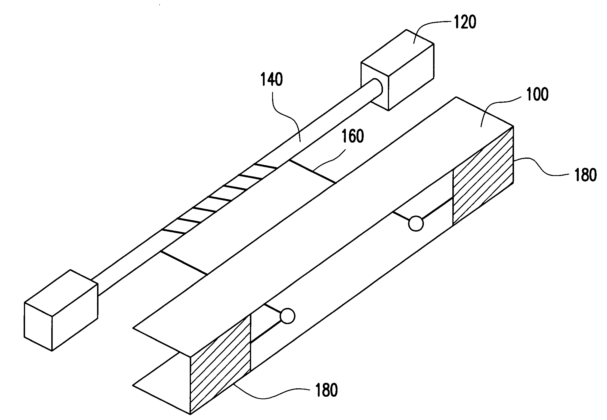
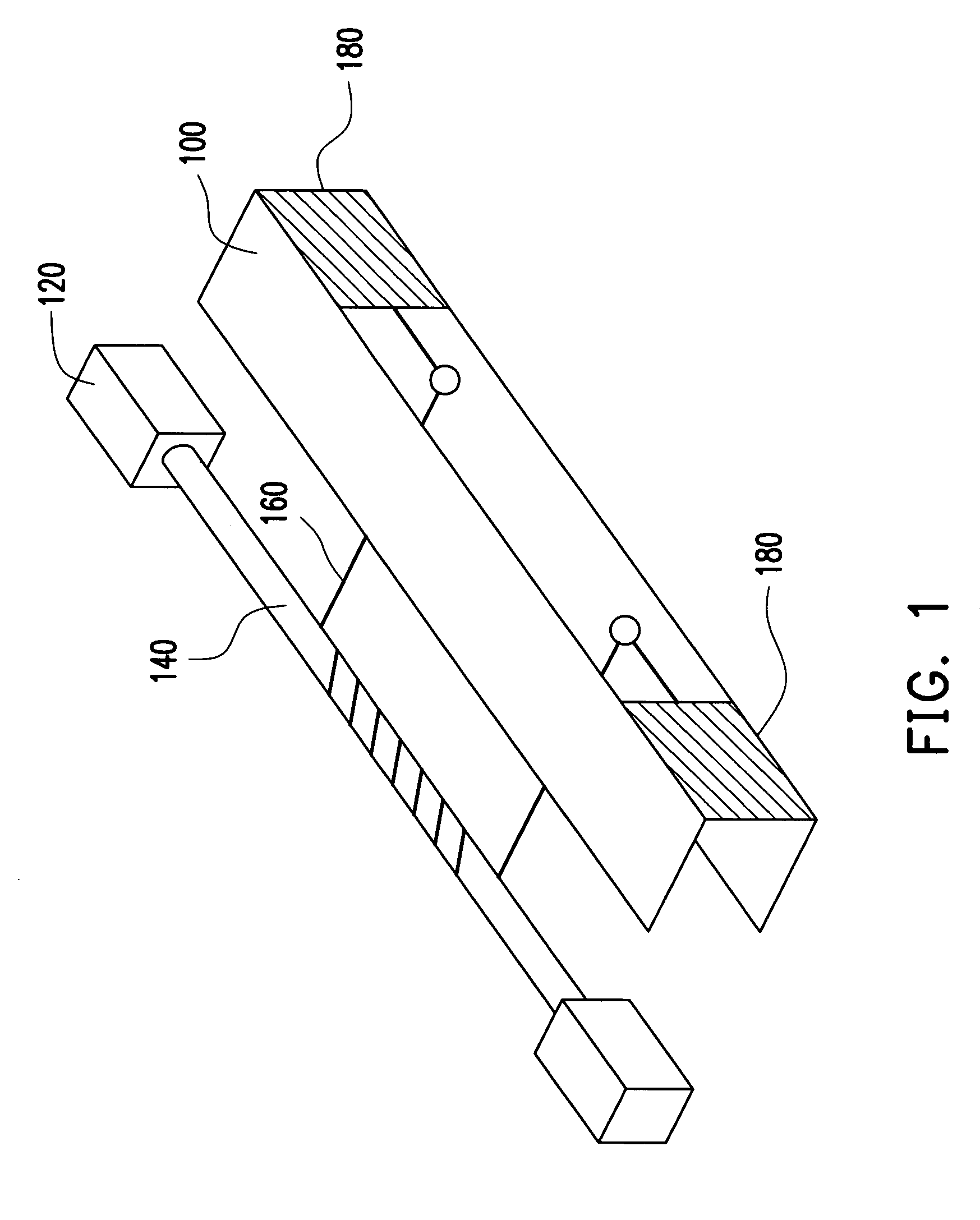
[0028]FIG. 1 schematically shows a perspective view of a light source module according to a first embodiment of the present invention. As shown in FIG. 1, the light source module includes a lamp cover 100, a lamp 140 and a conductive wire 160. The lamp 140 can be fastened on the lamp cover 100 by using fastening units 120 made of a rubber material, for example. The lamp cover 100 can be comprised of a light-reflective material, such as metal. The lamp 140 can be a cold cathode fluorescence lamp (CCFL), for example. The conductive wire 160 is wound onto a tube wall 142 of the lamp 140 and has two ends connected to the lamp cover 100. The lamp cover 100 includes two heat conductive plates 180 connected with two ends of the conductive wire 160, respectively.
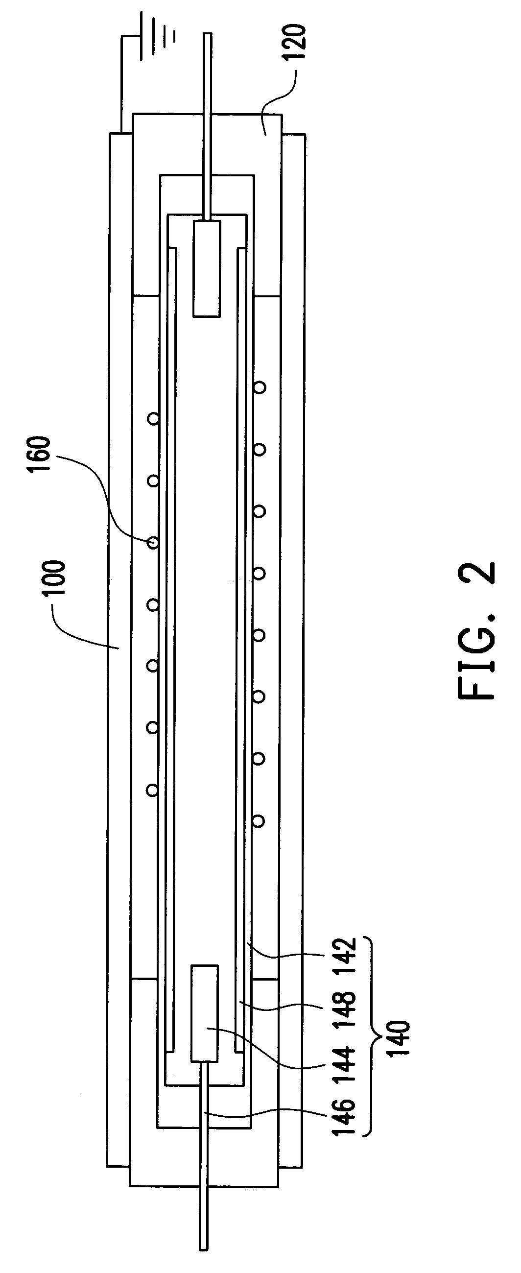
[0029]FIG. 2 is a schematic cross-sectional view of a light source module according to a first embodiment of the present invention. As shown in FIG. 2, the lamp 140 includes a tube wall 142, electrodes 144, lead ...
second embodiment
THE SECOND EMBODIMENT
[0031]In the above embodiment, a conductive wire connects the surface of the lamp, and the lamp cover to the ground and thereby the capacitance there-between can be substantially eliminated. However, the present invention is not limited to the above embodiment, a transparent conductive layer can also be used in conjunction with a conductive wire for eliminating the capacitance between the lamp and the lamp cover as described in the following second embodiment of the present invention.
[0032]FIG. 3 is a schematic cross-sectional view of a light source module according to a second embodiment of the present invention. As shown in FIG. 3, the structure of the light source module of the second embodiment is similar to the first embodiment except for a transparent conductive layer 270 formed on the tube wall 142 of the lamp 140, which is not electrically connected to the electrodes 144. A conductive wire260 is wound onto the transparent conductive layer 270 and the two...
third embodiment
THE THIRD EMBODIMENT
[0035]It the above first and second embodiment, the present invention respectively shows the use of the conductive wire to connect the surface of the lamp, and the lamp cover to the ground in order to eliminate the capacitance between the lamp and the lamp cover, and the use of the transparent conductive film in conjunction with the conductive wire to respectively improve the heat dissipation and eliminate the capacitance between the lamp and the lamp cover. The conductive wire is wound around the lamp with a fixed winding pitch. However, the present invention is not limited to winding the conductive wire around the lamp with a fixed pitch. Alternatively, the conductive wire can be wound with different pitches, the conductive wire wound with different pitches around the lamp can improve the heat dissipation. The detail is described as below.
[0036]FIG. 5 is a cross-sectional view of a light source module according to a third embodiment of the present invention. As...
PUM
| Property | Measurement | Unit |
|---|---|---|
| distance | aaaaa | aaaaa |
| conductive | aaaaa | aaaaa |
| volume | aaaaa | aaaaa |
Abstract
Description
Claims
Application Information
 - R&D
- Intellectual Property
- Life Sciences
- Materials
- Tech Scout
- Unparalleled Data Quality
- Higher Quality Content
- 60% Fewer Hallucinations
Browse by: Latest US Patents, China's latest patents, Technical Efficacy Thesaurus, Application Domain, Technology Topic, Popular Technical Reports.
© 2025 PatSnap. All rights reserved.Legal|Privacy policy|Modern Slavery Act Transparency Statement|Sitemap|About US| Contact US: help@patsnap.com


