
Method for the operation of a digital, programmable hearing aid as well as a digitally programmable hearing aid

a hearing aid and programmable technology, applied in the direction of deaf-aid sets, electric devices, etc., can solve the problems of inability to achieve the gain of hearing aids due to a more pronounced hearing impairment, and the user's experience of whistling is usually extremely unpleasant, and achieves a wide frequency response

Inactive Publication Date: 2006-06-27
SIVANTOS PTE LTD
View PDF11 Cites 35 Cited by
  • Summary
  • Abstract
  • Description
  • Claims
  • Application Information

AI Technical Summary

Benefits of technology

[0011]An object of the present invention is to provide a method for operating a hearing aid as well as to provide a hearing aid that allows a broad frequency response.
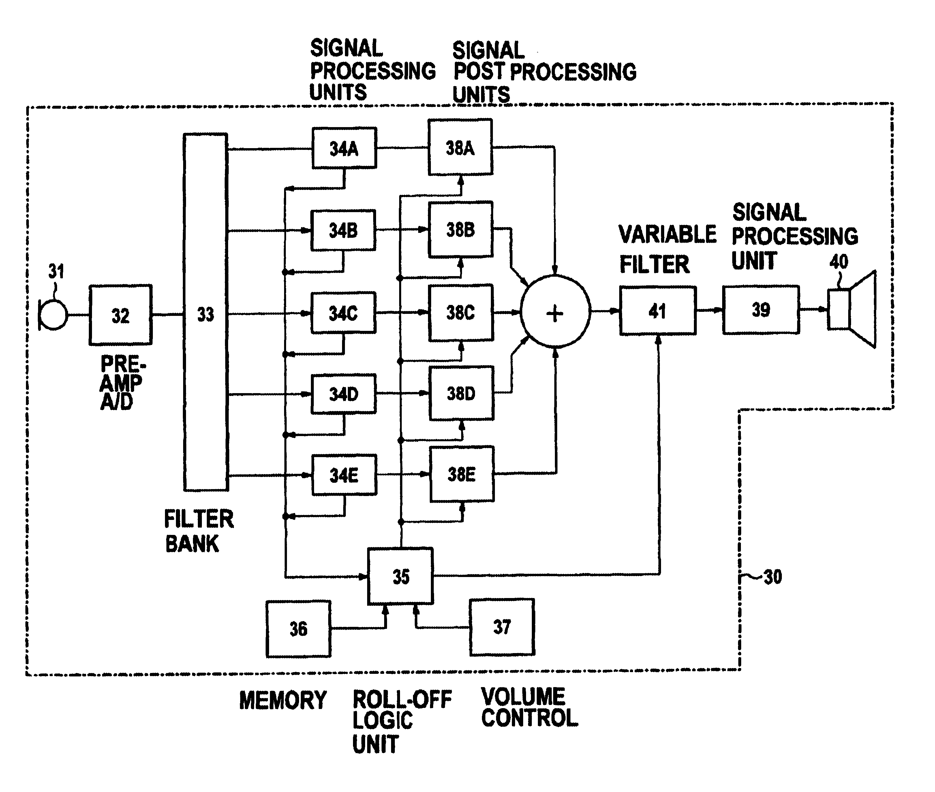
[0015]The hearing aid comprises an input transducer for picking up an input signal. A microphone normally serves as an input transducer, this picking up an acoustic signal and converting it into an electrical audio signal. However, the invention can use other types of input transducers such as those that comprise a coil or an antenna and that pick up an electromagnetic signal and convert it into an electrical audio signal. The hearing aid of the invention also comprises a signal processing unit for the processing and frequency-dependent amplification of the audio signal. The signal processing in the hearing aid ensues using a digital signal processor (DSP) whose operation can be influenced by programs or parameters that can be transmitted to the hearing aid. This permits the operation of the signal processing unit to be adapted to the individual hearing impairment of a hearing aid user as well as to the current auditory situation in which the hearing aid is operated at the moment. The audio signal varied in this way is finally supplied to an output transducer. This is usually fashioned as an earphone that converts the electrical audio signal into an acoustic signal. However, other embodiments are also possible here, for example, an implantable output transducer that is directly connected to an ossicle and causes it to oscillate.
[0022]The invention offers the advantage that a nearly arbitrary, normal amplification as well as a nearly arbitrary, maximum amplification for a specific hearing aid can be set as a result. The signal processing in the hearing aid can thus be adapted better both to hearing aid-specific conditions as well as to the individual hearing impairment of a hearing aid user. The invention also offers the advantage that a plurality of influencing factors that simultaneously influence the amplification (for example, current setting of the volume control, gain modification using a signal processing algorithm, maximum amplification that has been set) can be taken into consideration more effectively.
[0023]One embodiment of the invention provides that the signal processing ensues in a plurality of parallel frequency channels of the signal processing unit, and the transmission characteristic of the normal amplification of the audio signal over the frequency range and / or the transmission characteristic of the maximum amplification of the audio signal over the frequency range can be separately set for the respective channel. The division of the audible frequency range into a plurality of channels facilitates the adaptation of a hearing aid when characteristic quantities relating to a specific channel (i.e., a specific frequency range) are viewed as being constant for this channel. Such characteristic quantities for a specific channel can be the hearing threshold, the discomfort threshold, but can also be the normal amplification or the maximum amplification. Only specifying a value for the appertaining channel is then required for the characterization.

Problems solved by technology

This “whistling” is usually extremely unpleasant both for the hearing aid user as well as for persons in the immediate proximity.
The critical disadvantage of this approach, however, is that the hearing aid gain required given a more pronounced hearing impairment can no longer be achieved as a result of this limitation.

Method used


Image

  • Method for the operation of a digital, programmable hearing aid as well as a digitally programmable hearing aid
  • Method for the operation of a digital, programmable hearing aid as well as a digitally programmable hearing aid
  • Method for the operation of a digital, programmable hearing aid as well as a digitally programmable hearing aid

Examples


Embodiment Construction

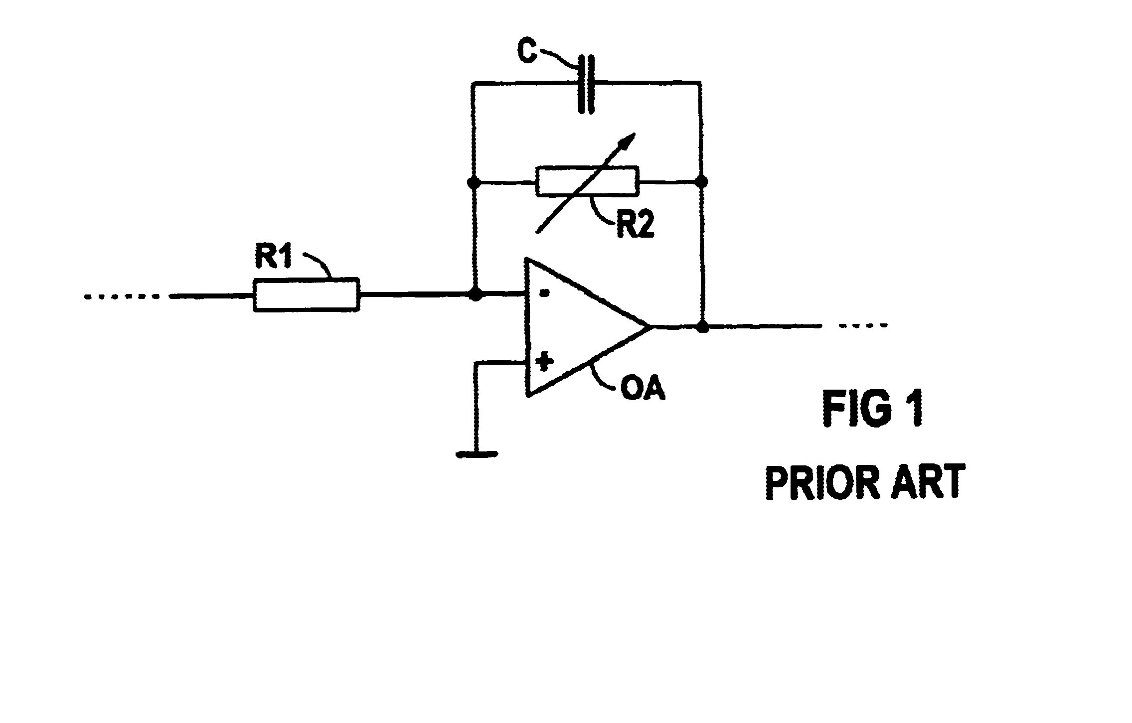
[0031]FIG. 1 shows the circuit-oriented realization of a roll-off circuit in a hearing aid with analog signal processing. This amplifier circuit comprises an operational amplifier OA that is wired with an input resistor R1 as well as with an RC element composed of a potentiometer R2 and a capacitor C in the feedback branch. The gain and, thus, the volume setting at the hearing aid, can be modified with the potentiometer R2. Simultaneously with the gain, however, the limit frequency (the knee point) from which the gain decreases with increasing frequency also changes.

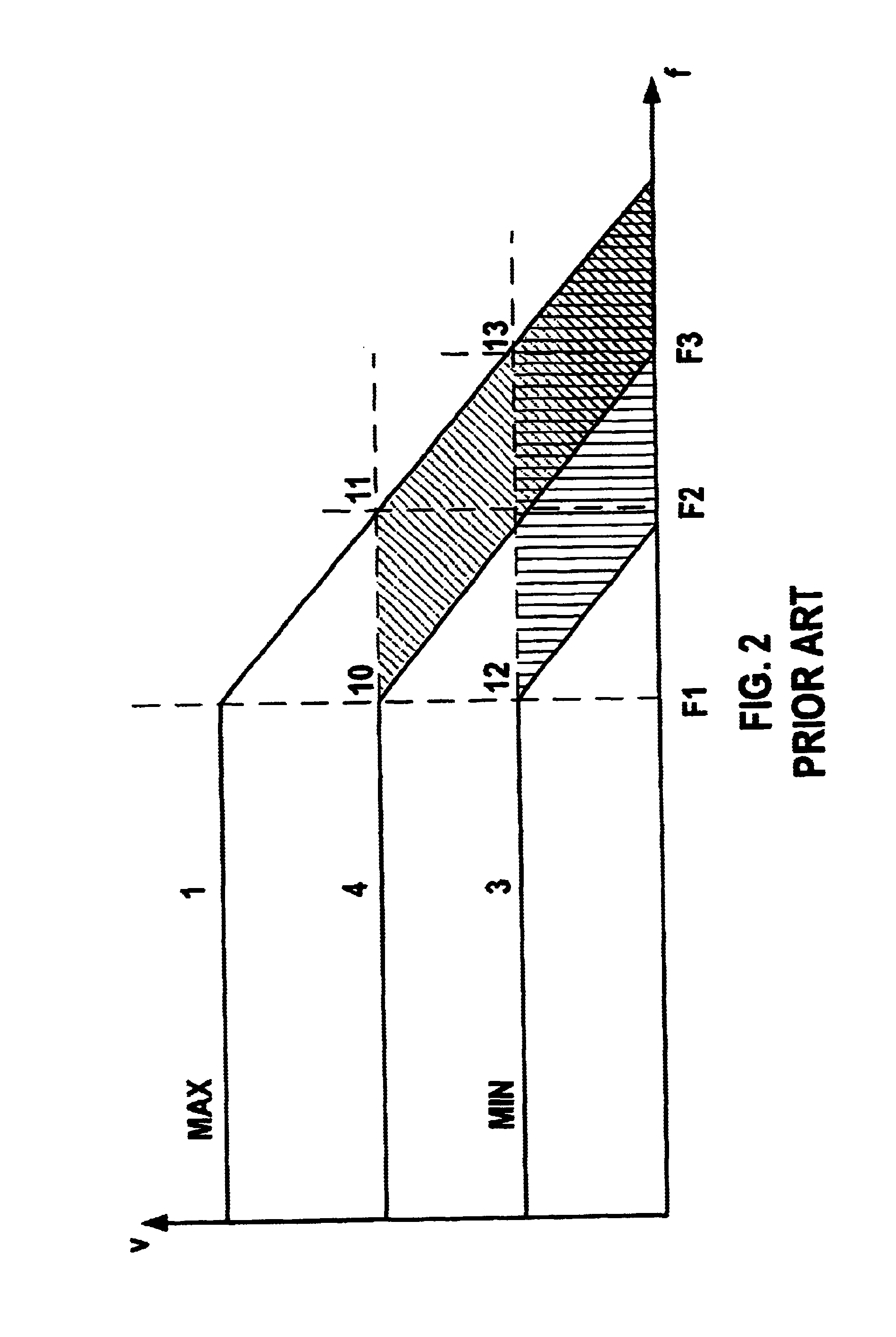
[0032]FIG. 2 shows the amplification V over the frequency f for different potentiometer settings of the amplifier circuit according to FIG. 1. The characteristic 1 shows the amplification V over the frequency f at the maximum volume setting at which the resistance of the potentiometer R2 is at its highest value. The amplification is constant up to a limit frequency F1; the amplification decreases linearly with increasing...


PUM


Abstract

A method for operating a digital, programmable hearing aid is provided that uses both a transmission characteristic of a normal amplification as well as a transmission characteristic of a maximum amplification of an audio signal over a frequency range that can be nearly freely configured. Given a modification of the amplification by settings at the hearing aid as well as using parameters that result from the signal processing, the gain for the overall system is always calculated utilizing all parameters and is potentially limited to the maximum amplification at the respective frequency if this would otherwise be exceeded.

Description

BACKGROUND OF THE INVENTION[0001]1. Field of the Invention[0002]The invention is directed to a method for the operation of a digital, programmable hearing aid having an input transducer for picking up an input signal and converting it into an audio signal, having a signal processing unit for the processing and frequency-dependent amplification of the audio signal, and having an output transducer. The invention is also directed to a digital, programmable hearing aid for implementing the method.[0003]2. Description of the Related Art[0004]Acoustic feedback frequently occurs in hearing aid devices, particularly for hearing aid devices having a high gain. This feedback is expressed in strong, feedback-caused oscillations at a specific frequency (feedback). This “whistling” is usually extremely unpleasant both for the hearing aid user as well as for persons in the immediate proximity.[0005]Feedback can occur when sound that is picked up via the microphone of the hearing aid device, ampli...

Claims


Application Information

Patent Timeline
IPC IPC(8): H04R25/00
CPCH04R25/453H04R25/505
Inventor SCHULZ, HERVEWEIDNER, TOM
Owner SIVANTOS PTE LTD
Learn More