
Embedded chirp signal for position determination in cellular communication systems

a cellular communication system and embedded chirp technology, applied in the direction of instruments, sustainable buildings, amplitude demodulation, etc., can solve the problems of inability to provide the requisite accuracy, difficulty in meeting fcc e911, the most demanding ali requirement, and lack of automatic coupling of such a solution into the return link to the base station, etc., to achieve accurate determination of the position of a mobile station

Active Publication Date: 2006-06-27
ITT CORP
View PDF32 Cites 88 Cited by
  • Summary
  • Abstract
  • Description
  • Claims
  • Application Information

AI Technical Summary

Benefits of technology

[0015]Therefore, in light of the above, and for other reasons that will become apparent when the invention is fully described, an object of the invention is to accurately determine the position of a mobile station within a wireless communication network.

Problems solved by technology

As long as GPS operated in its intentionally degraded Selective Availability (SA) mode, it was incapable of providing the requisite accuracy.
Progress in meeting FCC E911, the most demanding ALI requirement, has been difficult to make.
And even though a handset might know its position to sufficient accuracy from an internally or externally supplied post-SA GPS solution, no means to automatically couple such a solution into the return link to the base station was provided.
Theory and experiment indicate that conventional systems performing ranging using the communication signals above are not able to meet the most stringent of the position determination accuracy requirements, e.g. E911.
Performance improvements are made possible by an embedded navigation signal, but the consequent dependence on external timing in the conventional systems creates an equipment burden at both the base station and the mobile stations that hampers backward compatibility.
Further, such dependence is disadvantageous in that outage of the timing reference system impairs or disables the position determination function.

Method used


Image

  • Embedded chirp signal for position determination in cellular communication systems
  • Embedded chirp signal for position determination in cellular communication systems
  • Embedded chirp signal for position determination in cellular communication systems

Examples


Embodiment Construction

[0047]Preferred embodiments according to the present invention are described below with reference to the above drawings, in which like reference numerals designate like components.

Overview

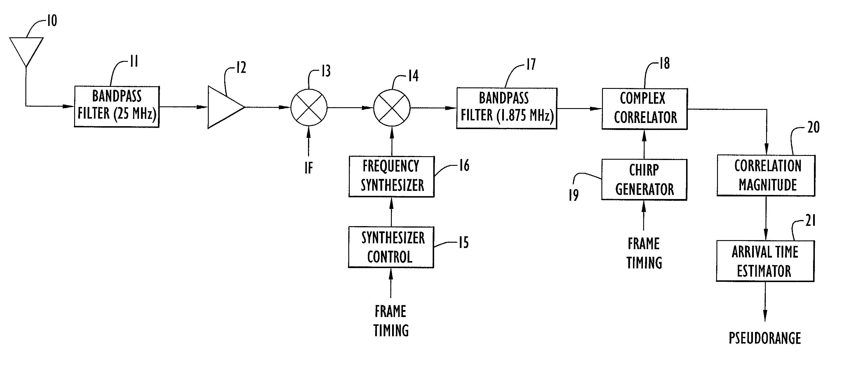
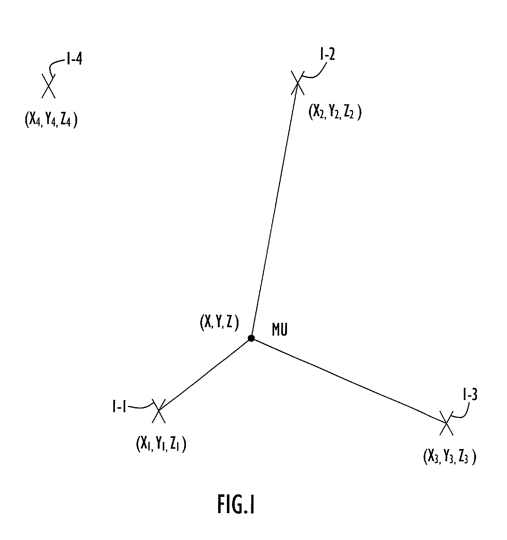
[0048]Systems and methods are described here for locating the position of a mobile terminal in a cellular communication system, such as the Global System for Mobile Communications (GSM). The communication system includes a network of transmitting and receiving base stations, at least one mobile unit and signals transmitted between the base station and the mobile station. Time-division-multiplex / frequency-division-multiple-access (TDM / FDMA) communication signals are examples of signals the base stations transmit to mobile units. In addition the base stations can also transmit a linear frequency modulated (FM), or chirp signal that is synchronized to the communications frame structure of the base station. The chirp signal can include an up-chirp portion for one frame followed by a down-chirp portion ...


PUM


Abstract

Systems and methods are described here for locating the position of a mobile terminal in a cellular communications system. A base station in the cellular communication system broadcasts a communication signal having embedded therein a navigation signal. The navigation signal uses a chirp technique in which the chirp signal includes two portions, an up-chirp portion and a down-chirp portion. Each portion of the chirp signal is synchronized with a frame in the communication signal. The chirp navigation signal is at a power level much lower than the communication signal so as not to interfere with the communication signal. A mobile terminal generates a corresponding chirp signal to correlate with the incoming signal and to extract the navigation signal. The mobile terminal uses the detected navigation signal to determine a time of arrival of the communication signal for use in determining the position of the mobile terminal either at the terminal or to send to a network center for location processing.

Description

CROSS REFERENCE TO RELATED APPLICATION[0001]This application claims precedence from U.S. Provisional Patent Application Ser. No. 60 / 325,025 entitled “An Embedded Chirp Signal for Position Determination in Cellular Communication Systems,” filed Sep. 26, 2001. The disclosure of that provisional patent application is incorporated by reference here in its entirety.BACKGROUND OF THE INVENTION[0002]1. Field of the Invention[0003]This invention relates to position determination of mobile users in a wireless communication system. More particularly, it relates to cellular communication systems in which position determination is provided as a low-complexity, augmentation service to an installed base of communication equipment.[0004]2. Description of the Related Art[0005]Mobile communication services have grown from infancy in the 1970s to become world wide in scope, having subscribers in numbers threatening to overcome the size of the fixed telephone base. First generation (1G) analog systems...

Claims


Application Information

Patent Timeline
Patent Type & Authority Patents(United States)
IPC IPC(8): H04B1/69H04M11/04G01S19/46G01S5/02G01S5/14H04W64/00
CPCG01S5/02G01S5/0215H04W64/00G01S5/0221Y02B60/50G01S5/145G01S5/0218
Inventor ORR, RICHARD S.
Owner ITT CORP
Learn More