Strain tolerant aggregate material

a technology of aggregate materials and aggregates, applied in the direction of wind motors with parallel air flow, wind motors with perpendicular air flow, liquid fuel engine components, etc., can solve the problems of ineffective backside closed-loop cooling as a protection technique for materials, generally not as strong as metals, and large cross-sectional area of specific applications

Inactive Publication Date: 2006-06-27
SIEMENS ENERGY INC
View PDF49 Cites 23 Cited by
  • Summary
  • Abstract
  • Description
  • Claims
  • Application Information

AI Technical Summary

Problems solved by technology

However, CMC materials generally are not as strong as metal, and therefore the required cross-section for a particular application may be relatively thick.
Due to the low coefficient of thermal conductivity of CMC materials and the relatively thick cross-section necessary for many applications, backside closed-loop cooling is generally ineffective as a cooling technique for protecting these materials in combustion turbine applications.
It is generally very difficult to form such complex cooling passages in a ceramic matrix composite component.
Such large chambers create an internal pressure force that can result in the undesirable ballooning of the airfoil structure due to the internal pressure of the cooling fluid applied to the large internal surface area of the passage 18.

Method used


Image

  • Strain tolerant aggregate material
  • Strain tolerant aggregate material
  • Strain tolerant aggregate material

Examples


Embodiment Construction

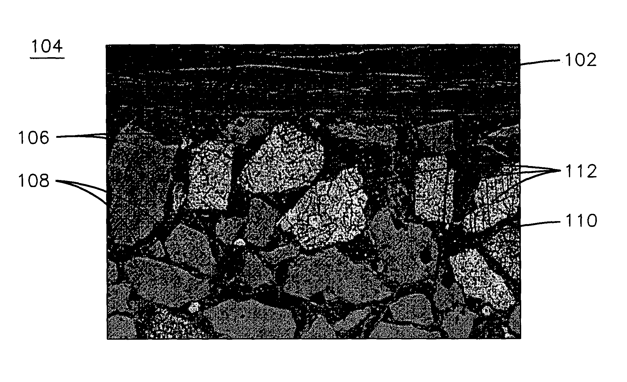
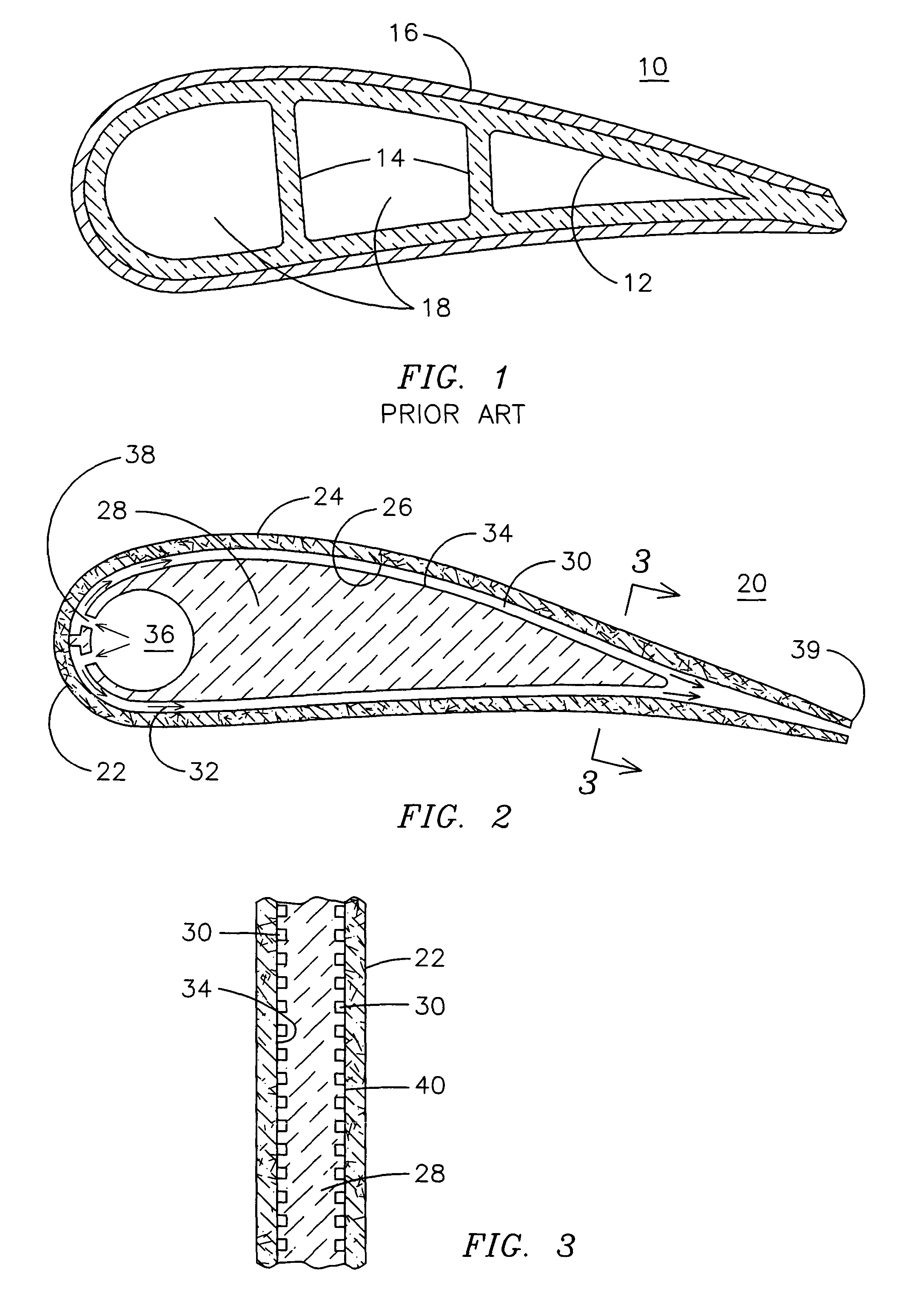
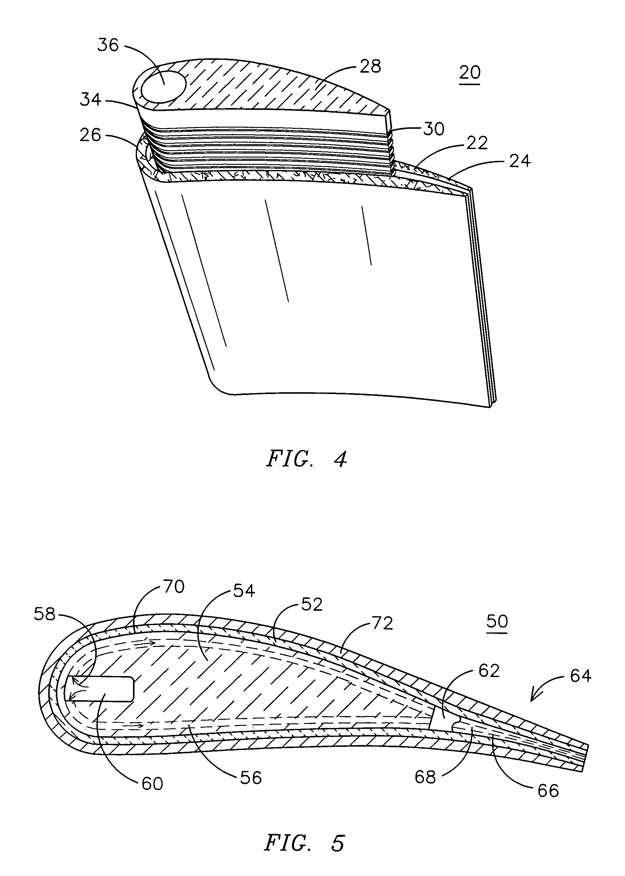
[0012]FIGS. 2–4 illustrate an improved stationary vane 20 for a gas turbine engine. The vane 20 includes an airfoil member 22 formed from a ceramic matrix composite material having an outer surface 24 defining an airfoil and an inner surface 26 defining a core region. The term ceramic matrix composite is used herein to include any fiber-reinforced ceramic matrix material as may be known or may be developed in the art of structural ceramic materials. The fibers and the matrix material surrounding the fibers may be oxide ceramics or non-oxide ceramics or any combination thereof. A wide range of ceramic matrix composites (CMCs) have been developed that combine a matrix material with a reinforcing phase of a different composition (such as mulite / silica) or of the same composition (alumina / alumina or silicon carbide / silicon carbide). The fibers may be continuous or discontinuous fibers and may take the form of whiskers, platelets or particulates. Reinforcing fibers may be disposed in the...


PUM

PropertyMeasurementUnit
Temperatureaaaaaaaaaa
Fractionaaaaaaaaaa
Fractionaaaaaaaaaa

Abstract

A material (100) formed of a sintered aggregation of ceria particles (106), mullite particles (108) and an alumina matrix material (110). Differential thermal expansion of the ceria and mullite particles generates thermal stress sufficient to create micro-cracking of the ceria particles. The ratio of ceria to mullite may be selected to achieve a desired coefficient of thermal expansion for matching the thermal growth of a mating CMC material (102). The micro cracks provide the material with a desired degree of strain tolerance useful in high temperature applications such as a solid core gas turbine vane (20).

Description

[0001]This application is a continuation-in-part of U.S. application Ser. No. 10 / 158,946 filed May 31, 2002, now U.S. Pat. No. 6,709,230, issued on Mar. 23, 2004.BACKGROUND OF THE INVENTION[0002]It is known to use ceramic matrix composite (CMC) materials in high temperature environments such as in the hot combustion gas flow path of a gas turbine engine. CMC materials offer the potential for higher operating temperatures than do metal alloy materials due to the inherent nature of ceramic materials. This capability may be translated into a reduced cooling requirement that, in turn, may result in higher power, greater efficiency, and / or reduced emissions from the machine. However, CMC materials generally are not as strong as metal, and therefore the required cross-section for a particular application may be relatively thick. Due to the low coefficient of thermal conductivity of CMC materials and the relatively thick cross-section necessary for many applications, backside closed-loop c...

Claims


Application Information

Patent Timeline
IPC IPC(8): C04B35/50B32B9/00C04B35/185F01D5/18F01D5/28
CPCF01D5/189F01D5/282F01D5/284F01D5/288Y10T428/252F05D2300/6033F05D2300/50212Y10T428/257C04B37/001C04B37/008C04B2237/343C04B2237/38C04B2237/62C04B2237/84Y02T50/60
Inventor CAMPBELL, CHRISTIAN X.
Owner SIEMENS ENERGY INC
Why Eureka
Try Eureka