Safety ski binding incorporating a toe and a heel binding and an electronic circuit arrangement

a technology of electronic circuit and safety ski binding, which is applied in the direction of ski bindings, skis, sports apparatus, etc., can solve the problems of low output range, inability to detect changes in safety release values, and high interference sensitivity of electronic components, so as to achieve accurate and conclusive evaluation, easy and automatic recording, and maintain the effect of functional and operating safety of safety ski bindings

Inactive Publication Date: 2006-06-20
ATOMIC AUSTRIA
View PDF11 Cites 28 Cited by
  • Summary
  • Abstract
  • Description
  • Claims
  • Application Information

AI Technical Summary

Benefits of technology

[0009]One of the advantages of the ski binding proposed by the invention is the fact that the safety setting, in particular the so-called Z numbers, are electronically acquired or recorded and stored in the non-volatile memory system for subsequent checking or control. This means, for example, that an authorised control point or optionally the user of the safety ski binding can check at any time to ascertain whether the originally valid or set safety values have been changed. By storing the relevant data in a memory system co-operating with a micro-controller, the electronically detected setting values can be subsequently manipulated, e.g. to record any unauthorised attempt to tamper with what was a correctly set safety ski binding which might otherwise be misleading or confusing, because an unauthorised change made to the settings in the ski binding is recorded. Furthermore, because the memory system co-operates with a micro-controller, the data stored in it is particularly well protected in terms of external unauthorised access or tampering. Accordingly, the safety ski binding has what is in effect an “electronic log book”, by means of which authorised persons and optionally the user of the safety ski binding can see any changes and ascertain the current status of the safety sky binding. Another significant advantage of this system is that it provides a means of checking the currently prevailing status and safety settings in the event of product liability claims, in which case the recorded data can be used to get to the bottom of the situation.
[0020]Finally, in another embodiment of the safety ski binding, the transmitter and / or receiver device or the interface and contacts are configured for transmitting data signals to an electronic computer unit and / or for receiving data signals from a peripheral electronic computer unit, in particular a wrist-top computer, a handheld computer, a mobile telephone or any other mobile electronic unit, the advantage of which is that it obviates the need for structurally complex and cost-intensive input means on the electronic ski binding. This specifically means that a stand-alone electronic computer unit is used as the programming and / or operating and / or display means for the electronic system in the safety ski binding. Since nothing or only very simple means are needed for input purposes, there will barely be any problems in terms of external disruptive influences, such as liquids, vibration, mechanical stress and similar. Moreover, this all adds to the functionality, versatility and user convenience, whilst facilitating maintenance work, servicing and adaptation to the electronic system of the safety ski binding.

Problems solved by technology

The disadvantage of this system is that an analogue signal evaluation of the virtually static or absolute position sensors is necessary, which means that the electronic components have a high sensitivity to interference and a low output range.
Although the currently set safety release value can be electronically detected and shown on a display with this system, it is not possible to detect changes in the safety release value.

Method used


Image

  • Safety ski binding incorporating a toe and a heel binding and an electronic circuit arrangement
  • Safety ski binding incorporating a toe and a heel binding and an electronic circuit arrangement
  • Safety ski binding incorporating a toe and a heel binding and an electronic circuit arrangement

Examples


Embodiment Construction

[0025]Firstly, it should be pointed out that the same parts described in the different embodiments are denoted by the same reference numbers and the same component names and the disclosures made throughout the description can be transposed in terms of meaning to same parts bearing the same reference numbers or same component names. Furthermore, the positions chosen for the purposes of the description, such as top, bottom, side, etc, relate to the drawing specifically being described and can be transposed in terms of meaning to a new position when another position is being described. Individual features or combinations of features from the different embodiments illustrated and described may be construed as independent inventive solutions or solutions proposed by the invention in their own right.

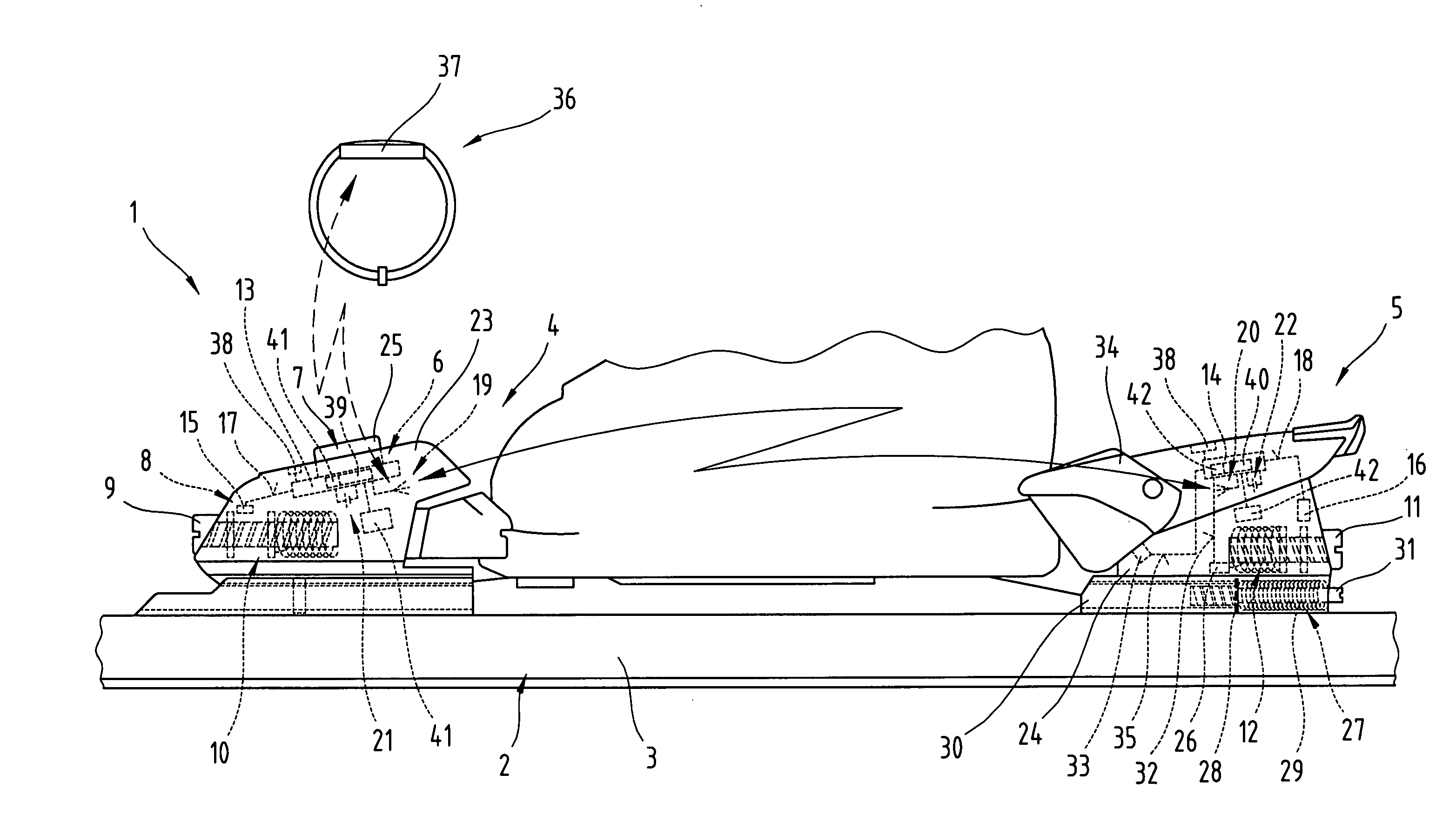
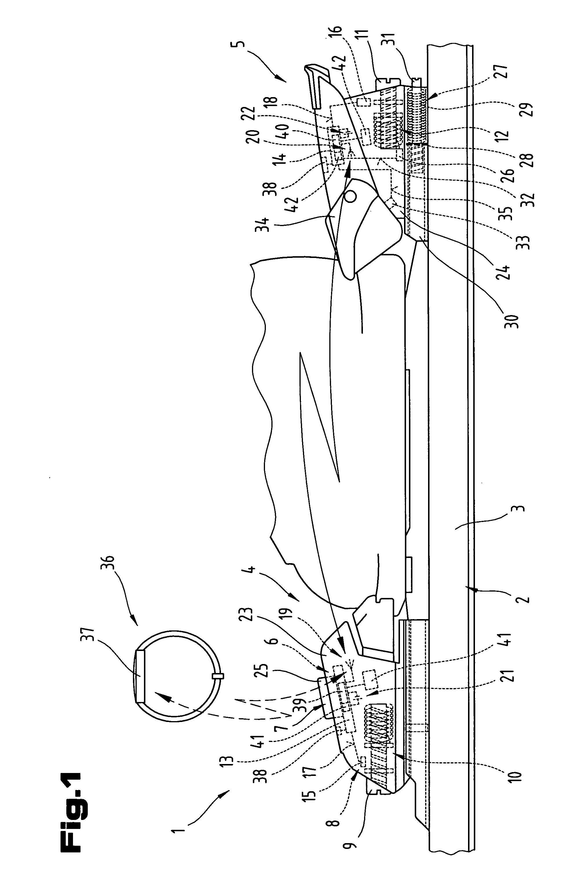
[0026]FIG. 1 is a highly simplified diagram symbolising one possible embodiment of a safety ski binding 1 as proposed by the invention. In a generally known manner, a safety ski binding 1 of t...


PUM


Abstract

The invention relates to a safety ski binding (1) with a toe and a heel binding (4, 5) and an electronic circuit arrangement (6). This circuit arrangement (6) comprises a computer unit and a memory system as well as a sensor system (8) for detecting at least one set safety release value of the safety ski binding (1). The circuit arrangement (6) has at least one electronic evaluation device (13, 14) with a software-driven, programmable micro-controller (39, 40), the micro-controller (39, 40) having a non-volatile memory system (41, 42) or being connected to a non-volatile memory system (41, 42). This micro-controller (39, 40) is programmed to store manually altered settings of the safety release value and / or changing states of the safety ski binding (1) detected by the sensor system (8) in the memory system (41, 42).

Description

BACKGROUND OF THE INVENTION[0001]1. Field of the Invention[0002]The invention relates to a safety ski binding incorporating a toe and a heel binding and an electronic circuit arrangement, with a computer unit and a memory system as well as a sensor system detecting at least one a set safety release value for the safety binding.[0003]2. The Prior Art[0004]Patent specification EP 0 469 453 A1 discloses a safety ski binding with an electronic device for displaying the set safety release force. A display is provided, which displays the values of settings detected and determined by a sensor and an electronic evaluation device. A power supply in the form of a battery is also provided, so that the electrical components can be supplied with power by activating and deactivating a switch. The sensor, by means of which the set safety release value, is detected is provided in the form of a position sensor, which delivers a characteristic electric sensor signal depending on the position of an ad...

Claims


Application Information

Patent Timeline
Patent Type & Authority Patents(United States)
IPC IPC(8): A63C9/08A63C9/088
CPCA63C9/088
Inventor HOLZER, HELMUT
Owner ATOMIC AUSTRIA
Why Eureka
Try Eureka