Electric power generating system for a vehicle
a technology of electric power generation and vehicle, which is applied in the direction of hybrid vehicles, electric generator control, instruments, etc., can solve the problems of power control operation becoming unstable, power generation suppression is not carried out, battery terminal voltage drops, etc., to achieve the effect of raising the power operation point of the voltage control device, suppressing power generation, and maintaining high output voltage of the power generator
- Summary
- Abstract
- Description
- Claims
- Application Information
AI Technical Summary
Benefits of technology
Problems solved by technology
Method used
Image
Examples
first embodiment
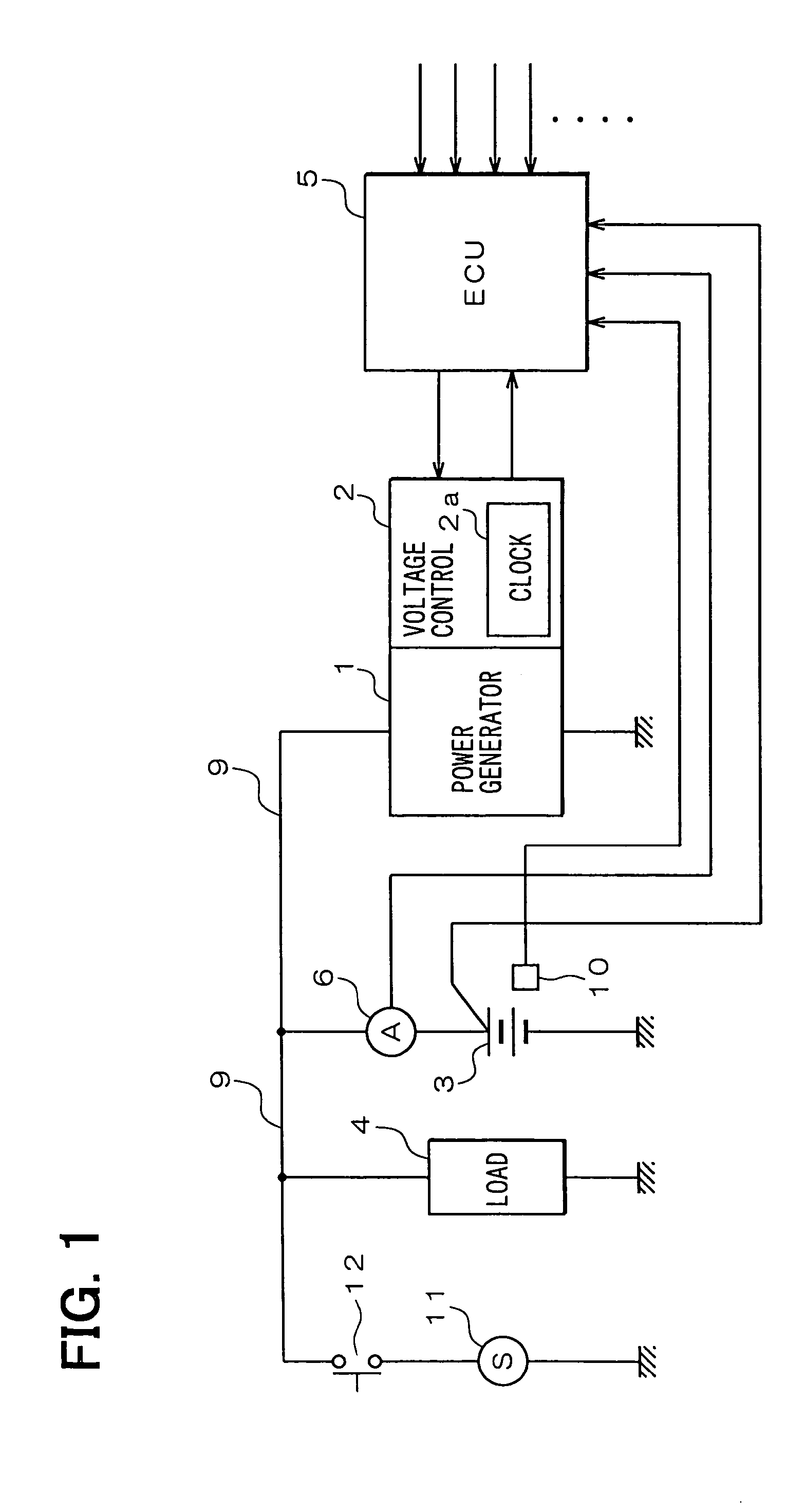
[0032]Referring first to FIG. 1, an electric power generating system for a vehicle is configured to have an electric power generator 1, a voltage control device 2, a battery 3, an electric load 4, and an electronic control unit (ECU) 5 for an internal combustion engine (not shown).
[0033]The power generator 1 is rotationally driven by the engine, and generates a charging electric power for the battery 3 and an operational electric power for the electric load 4.
[0034]The voltage control device 2 controls the power generator 1 to regulate an output voltage of the power generator 1 to a predetermined value by controlling a conductive state of an exciting current to a field coil in the power generator 1. In this voltage control device 2, a power supply circuit which generates operation voltages of constituent circuits, a power device such as a power transistor etc. for controlling conduction of the exciting current, a logic circuit for carrying out this conduction control and soon are re...
second embodiment
[0086]Since noise absorbing ability is lowered in case that the battery 3 is deteriorated, variation of the output voltage of the power generator 1 becomes larger. Also at this time, it is desirable to inhibit the output of the power generation suppression signal.
[0087]FIGS. 15A and 15B is a diagram showing changes of the battery terminal voltage due to presence or absence of deterioration of the battery 3. When the battery 3 is deteriorated, the internal impedance increases. The internal impedance of the battery 3 which is new and not deteriorated is R1 (FIG. 15A), and the internal impedance of the battery 3 which is deteriorated is R2 (FIG. 15B).
[0088]Assuming that a negative surge current which flows when the inductive electric load 4 is turned on or off is i, and an ideal terminal voltage of the battery 3 is Vbatt, the battery voltage Vb1 of the battery 3 which is not deteriorated becomes Vbatt−i×R1, and the battery voltage Vb2 of the battery 3 which is deteriorated becomes Vbat...
PUM
| Property | Measurement | Unit |
|---|---|---|
| discharge current IB1 | aaaaa | aaaaa |
| discharge current IB1 | aaaaa | aaaaa |
| time t1 | aaaaa | aaaaa |
Abstract
Description
Claims
Application Information
 - R&D
- Intellectual Property
- Life Sciences
- Materials
- Tech Scout
- Unparalleled Data Quality
- Higher Quality Content
- 60% Fewer Hallucinations
Browse by: Latest US Patents, China's latest patents, Technical Efficacy Thesaurus, Application Domain, Technology Topic, Popular Technical Reports.
© 2025 PatSnap. All rights reserved.Legal|Privacy policy|Modern Slavery Act Transparency Statement|Sitemap|About US| Contact US: help@patsnap.com


