
Recording tape cartridge

a tape cartridge and cartridge body technology, applied in the field of recording tape cartridges, can solve the problems of troublesome maintenance, high maintenance cost, and insufficient prevention

Active Publication Date: 2006-06-13
FUJIFILM HLDG CORP +1
View PDF12 Cites 10 Cited by
  • Summary
  • Abstract
  • Description
  • Claims
  • Application Information

AI Technical Summary

Benefits of technology

[0041]In consideration of the circumstances described above, an object of the present invention is to provide a recording tape cartridge which is capable of reliably locking a reel with a brake member and releasing the locking with a release member, and which is capable of reducing limitations that are applied to an engaging portion and a reel gear by provision of the release member.
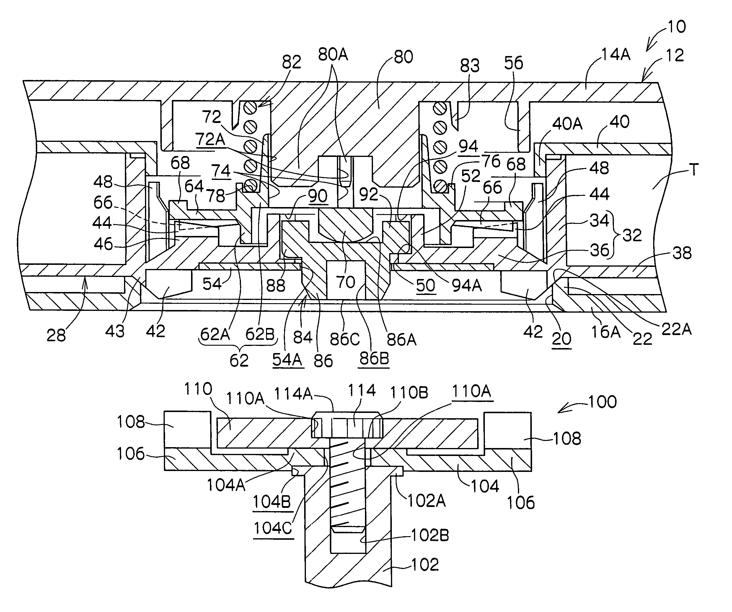
[0049]Further, because the operation portion of the release member faces the gear aperture from the radial direction inner side relative to the reel gear, there is no need to provide non-continuous portions at the reel gear for operating the release member. Thus, formation of the reel gear in a continuous annular form is enabled and, for example, an increase in torque that is transmitted from the driving gear and assurance of strength with respect to torque is expected.
[0052]Thus, with the recording tape cartridge of the first aspect, it is possible to reliably carry out locking of the reel with the brake member and release of the locking with the release member, and it is possible to restrain limitations on the engaging portion and the reel gear due to the provision of the release member.
[0054]In a recording tape cartridge of the present aspect, at least a portion of the main body portion (of the release member), which is disposed in a tubular portion of the reel hub at the radial direction inner side of the engaging member, is disposed in the through-hole which passes through the base portion of the reel hub. In other words, the at least a portion of the main body portion is disposed at a region of plate thickness of the base portion. Consequently, a protrusion height of the release member to the base portion inner face side is restrained. As a result, it is possible to provide the release member while keeping a position of engagement of the brake member with the engaging portion low.
[0056]According to the recording tape cartridge of the present aspect, at the time of releasing rotation-locking of the reel, the operation portion of the release member and the releasing portion of the drive device, which pushes the operation portion, are in surface contact. Consequently, wearing therebetween is reliably prevented.
[0059]Consequently, in a structure in which a magnetic plate provided at the outer face of the base portion of the reel hub is attracted by a magnet of the drive device, the operation portion provided at the axial center portion is less affected by attractive force from the magnet. That is, it is possible to structure the releasing portion separately from the magnet while maintaining the function of attraction by the magnet.

Problems solved by technology

However, if the releasing portion 212B of the drive device becomes worn, maintenance is troublesome and maintenance costs are high.
However, the area of the flat surface 223A is very small, so as to reduce the aforementioned sliding resistance, and is not large enough to prevent these vibrations.
Thus, arrangements of a motor and the like in the drive device are limited.
Thus, this release member is not a solution to the problems described above.
However, even the conventional recording tape cartridge 250 as described above has problems, as follows.
As a result, flow characteristics of resin during formation of the reel hub 210 that is formed of a usual resin are poor, which leads to a deterioration in formation characteristics.

Method used


Image

  • Recording tape cartridge
  • Recording tape cartridge
  • Recording tape cartridge

Examples


Embodiment Construction

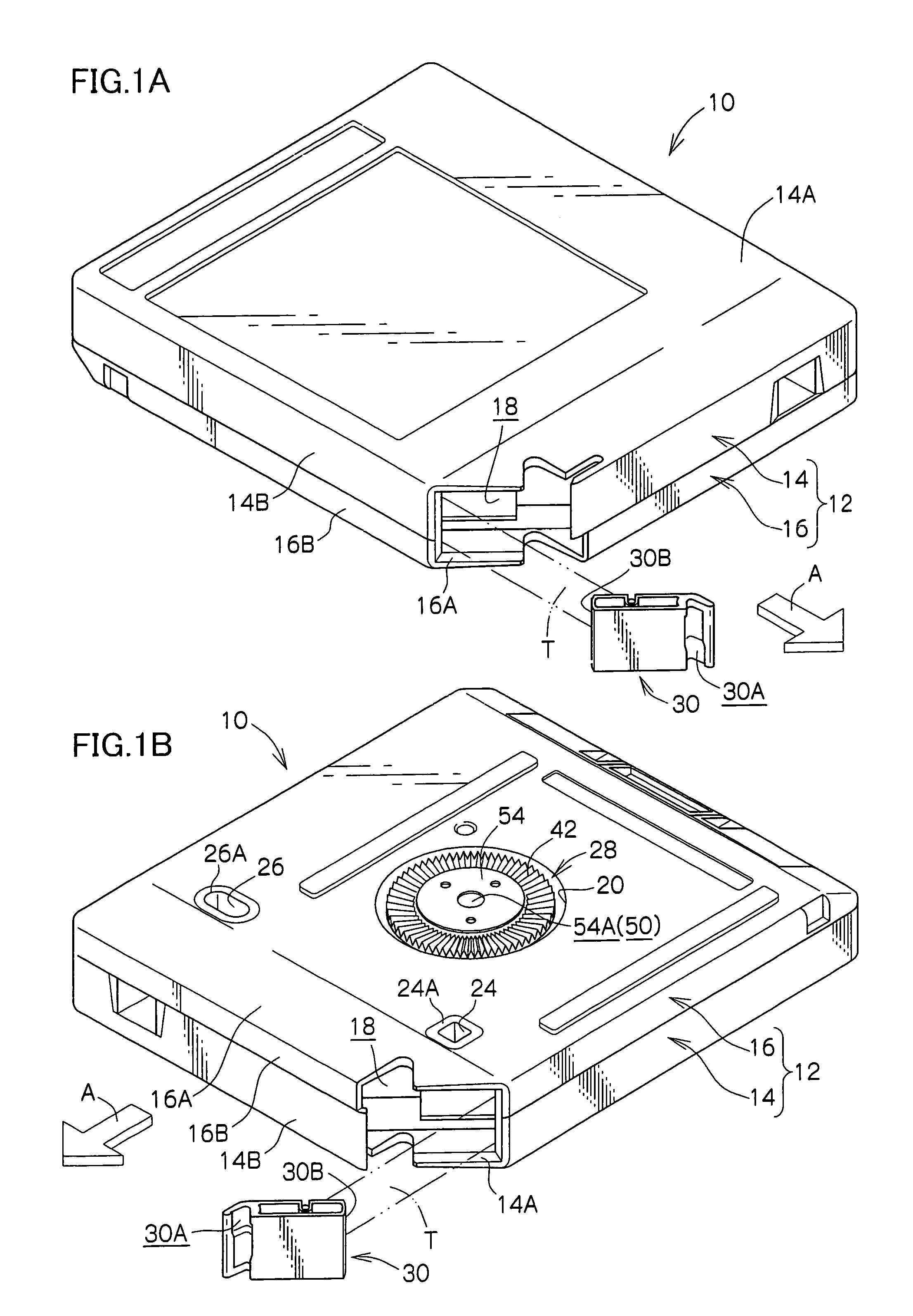
[0075]A recording tape cartridge 10 relating to an embodiment of the present invention will be described with reference to FIGS. 1 to 10.

[0076]FIG. 1A shows a perspective view, seen from diagonally above, of the recording tape cartridge 10 and FIG. 1B shows a perspective view, seen from diagonally below, of the recording tape cartridge 10. FIG. 2 shows a sectional view of the recording tape cartridge 10. Note that an arrow A shown in FIGS. 1A and 1B represents a direction of loading of the recording tape cartridge 10 into a drive device. For convenience of explanation, the side indicated by arrow A is referred to as the front side.

[0077]As shown in these drawings, the recording tape cartridge 10 is provided with a case 12. The case 12 is structured by joining together an upper case 14 and a lower case 16. More specifically, the upper case 14 is structured with a substantially frame-like peripheral wall 14B provided standing along outer edges of a ceiling plate 14A which is substanti...


PUM


Abstract

A recording tape cartridge in which a reel includes a reel gear and an engaging gear. The reel gear is formed in an annular shape at an outer face of a base portion of a reel hub. The engaging gear is formed in an annular shape at an inner face of the base portion. Magnetic tape is wound onto an outer periphery of the reel hub. A braking member is engaged with the engaging gear by an urging force and prevents the reel from rotating. A clutch member opposes a gear aperture at a radial direction inner side relative to the reel gear. An operationally pushed surface of the clutch member is pushed by a releasing surface of a drive device and the brake member is lifted, whereby rotation of the reel is enabled.

Description

CROSS-REFERENCE TO RELATED APPLICATION[0001]This application claims priority under 35 USC 119 from Japanese Patent Application No. 2003-187744, the disclosure of which is incorporated by reference herein.BACKGROUND OF THE INVENTION[0002]1. Field of the Invention[0003]The present invention relates to a recording tape cartridge which rotatably accommodates a reel onto which recording tape, such as a magnetic tape or the like, is wound.[0004]2. Description of the Related Art[0005]Recording tapes such as magnetic tapes and the like are used as external recording media for computers and the like. “One-reel” recording tape cartridges, which rotatably accommodate a single reel onto which a recording tape is wound in a case, can reduce space requirements for accommodation during storage and can record large amounts of information, and are employed as such recording tapes.[0006]Such a recording tape cartridge is equipped with a braking structure such that the reel does not rotate inside the ...

Claims


Application Information

Patent Timeline
IPC IPC(8): G11B23/07G11B15/32G11B23/04G11B23/107
CPCG11B15/32G11B23/107G11B23/043
Inventor HIRAGUCHI, KAZUOIINO, WATARUISHIHARA, YUSUKE
Owner FUJIFILM HLDG CORP
Learn More