
Device for measuring a tire pressure

a technology for measuring devices and tires, applied in vehicle tyre testing, instruments, roads, etc., can solve problems such as increasing the complexity of units, and achieve the effect of simplifying the pressure sensor units

Inactive Publication Date: 2006-06-13
CONTINENTAL AUTOMOTIVE GMBH
View PDF15 Cites 39 Cited by
  • Summary
  • Abstract
  • Description
  • Claims
  • Application Information

AI Technical Summary

Benefits of technology

The invention is a device for measuring tire pressure using a tire valve as an antenna. The device includes a tire pressure sensor unit that can be fastened in various angular positions relative to the valve. The electric connection between the sensor unit and the valve is made through an electric connection metal plate, which is pressed by a screw connection. The invention simplifies the design of the device by eliminating the need for a separate printed circuit board antenna and ensures a reliable electric connection. The device can be used with various rims and can be adjusted for easy installation.

Problems solved by technology

In another regard, however, disadvantages have to be noted, since a printed circuit board antenna requires installation space as an additional component of the tire pressure sensor unit, and increases the complexity of the unit.

Method used


Image

  • Device for measuring a tire pressure
  • Device for measuring a tire pressure
  • Device for measuring a tire pressure

Examples


Embodiment Construction

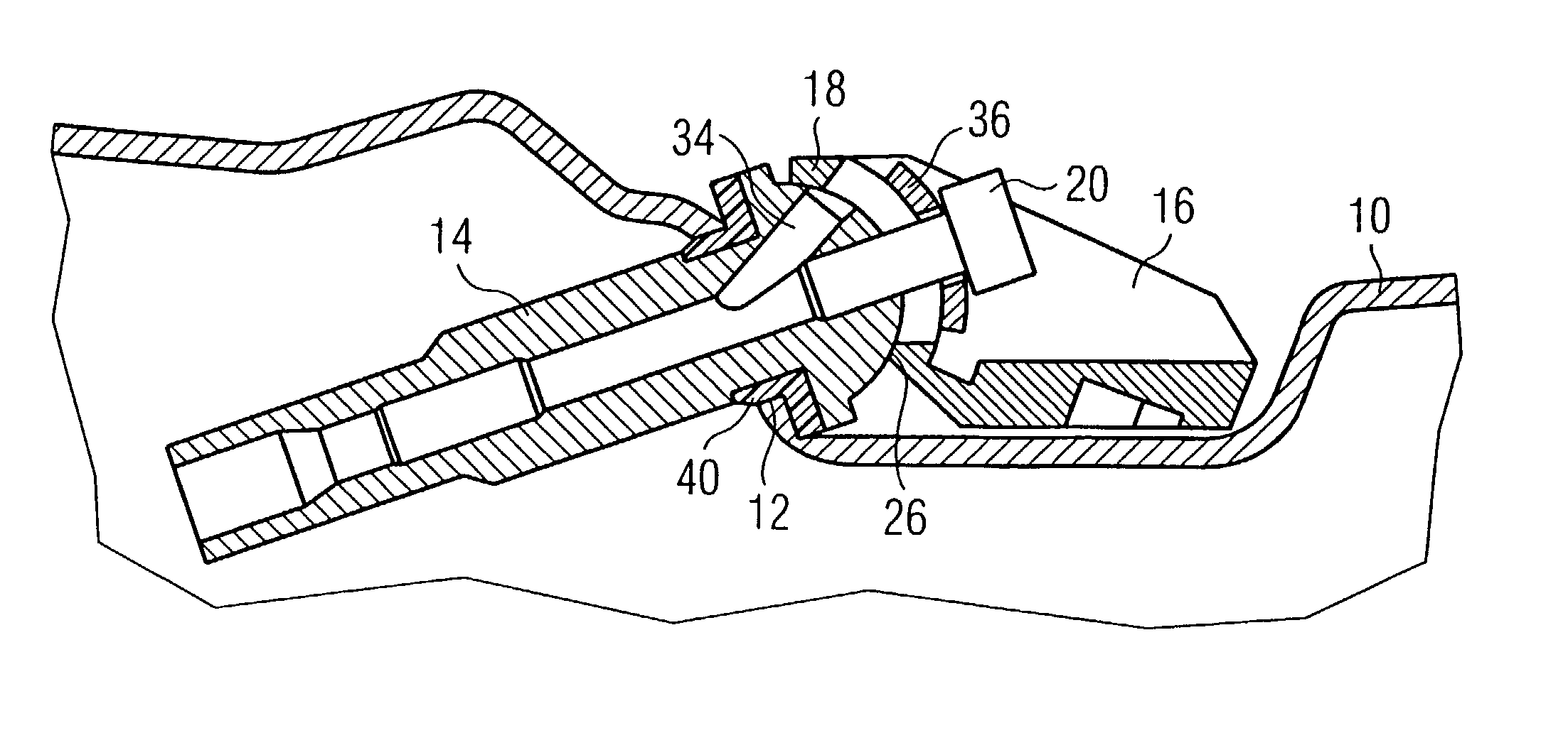
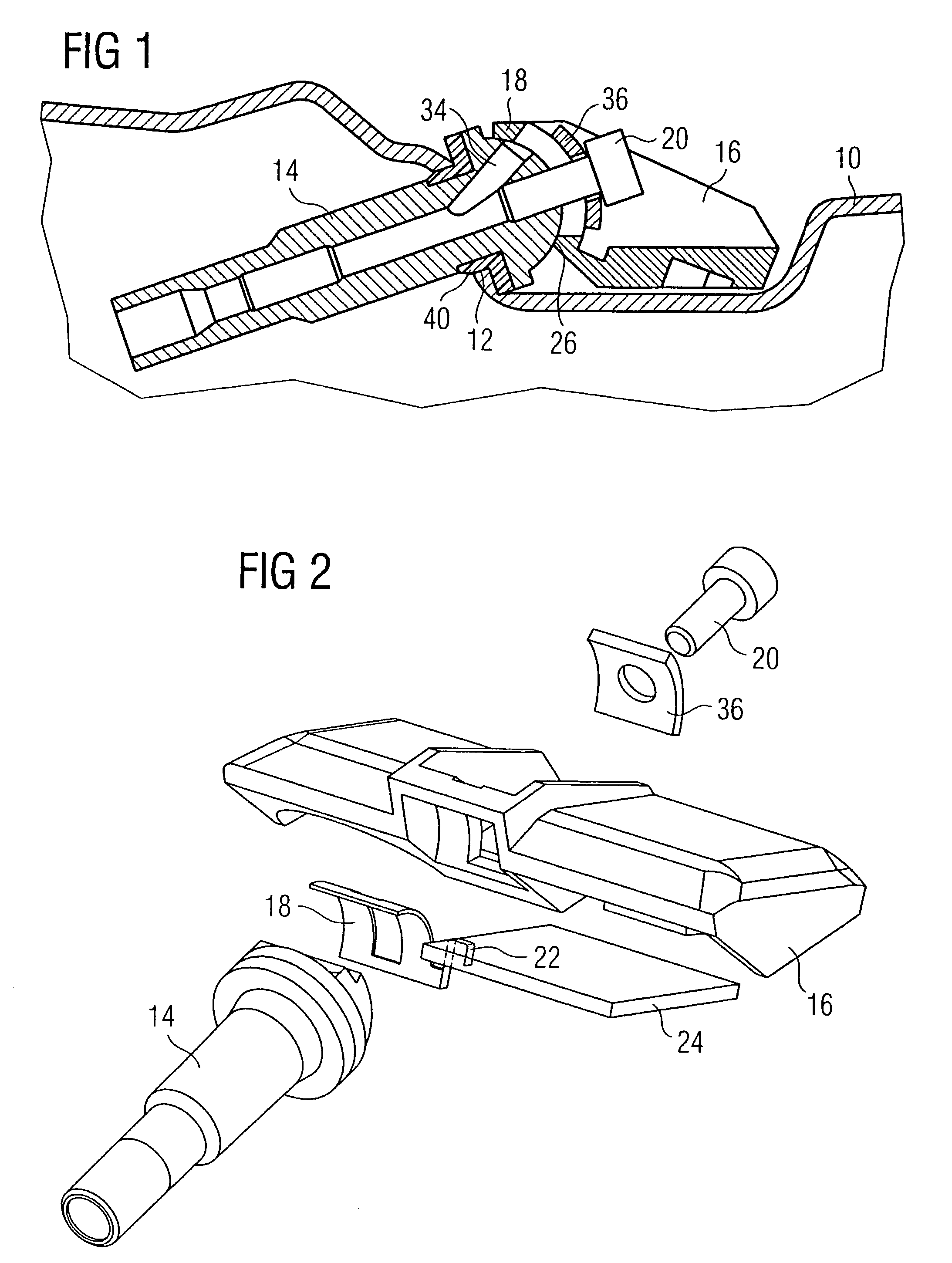
[0024]FIG. 1 shows a sectional view of a device according to the invention arranged in a tire. A rim 10 has a bore 12 for holding a tire valve 14. A tire valve 14 is inserted into this bore 12 and sealed with the aid of a seal 40. The valve 14 has a bypass bore 34 for bleeding. A tire pressure sensor unit 16 is arranged in the interior of the space formed by the rim 10 and the tire (not illustrated). Said unit is connected to the tire valve 14 via a cylindrical joint 26. The angular position of the tire pressure sensor unit 16 with reference to the tire valve 14 or with reference to the rim 10 is fixed by means of a screw 20.

[0025]Furthermore, a thin metal plate 18 is pressed onto the tire valve 14 by the screw 20. This metal plate 18 makes available an electric connection between a printed circuit board 24 (not illustrated in FIG. 1—see FIG. 2) and the tire valve 14. The tire valve 14 can function in this way as an antenna. The pressing of the metal plate 18 onto the tire valve 14 ...


PUM


Abstract

The invention relates to a device for measuring a tire pressure of a tire arranged on a rim (10), having a tire valve (14) arranged in a bore (12) in the rim (10), and a tire pressure sensor unit (16) arranged inside the tire and fastened on the tire valve (14), it being possible to fasten the tire pressure sensor unit (16) in various angular positions with reference to the tire valve (14).It is provided according to the invention that an electric connection (18) exists between the tire pressure sensor unit (16) and the tire valve (14), and that the tire valve (14) is provided as an antenna for communicating with a receiver and / or transmitter arranged outside the tire.

Description

CROSS-REFERENCE TO RELATED APPLICATION[0001]This application claims foreign priority benefits under 35 §U.S.C. 119 to German application number DE 10148876.9 filed Oct. 4, 2001.BACKGROUND OF THE INVENTION[0002]The invention relates to a device for measuring a tire pressure of a tire arranged on a rim, having a tire valve arranged in a bore in the rim, and a tire pressure sensor unit arranged inside the tire and fastened on the tire valve, it being possible, according to the embodiment, to fasten the tire pressure sensor unit in various angular positions with reference to the tire valve.[0003]Devices of this generic type are used in order to monitor the tire pressures in the tires of motor vehicles. This can be performed such that use is made of an automatic monitoring system that outputs warnings upon undershooting or overshooting of critical values. A device of the generic type is also used to indicate the tire pressures continuously in the interior of the vehicle.[0004]The measure...

Claims


Application Information

Patent Timeline
Patent Type & Authority Patents(United States)
IPC IPC(8): G01M17/02B60C23/04
CPCB60C23/0494B60C23/0408
Inventor FISCHER, MARTINLUCE, DOMINIQUEHILLENMAYER, FRANZ
Owner CONTINENTAL AUTOMOTIVE GMBH
Learn More