
Nonvolatile semiconductor memory device employing transistors having different gate withstand voltages for enhanced reading speed

a nonvolatile, memory device technology, applied in the direction of solid-state devices, digital storage, instruments, etc., can solve the problems of insufficient speeding up by hierarchized bit line structure based on main/sub bit lines, fragment gate type memory cells are not suitable for high-speed operation under low voltage, etc., to achieve the effect of improving the read speed and low cos

Inactive Publication Date: 2006-06-06
RENESAS ELECTRONICS CORP
View PDF25 Cites 65 Cited by
  • Summary
  • Abstract
  • Description
  • Claims
  • Application Information

AI Technical Summary

Benefits of technology

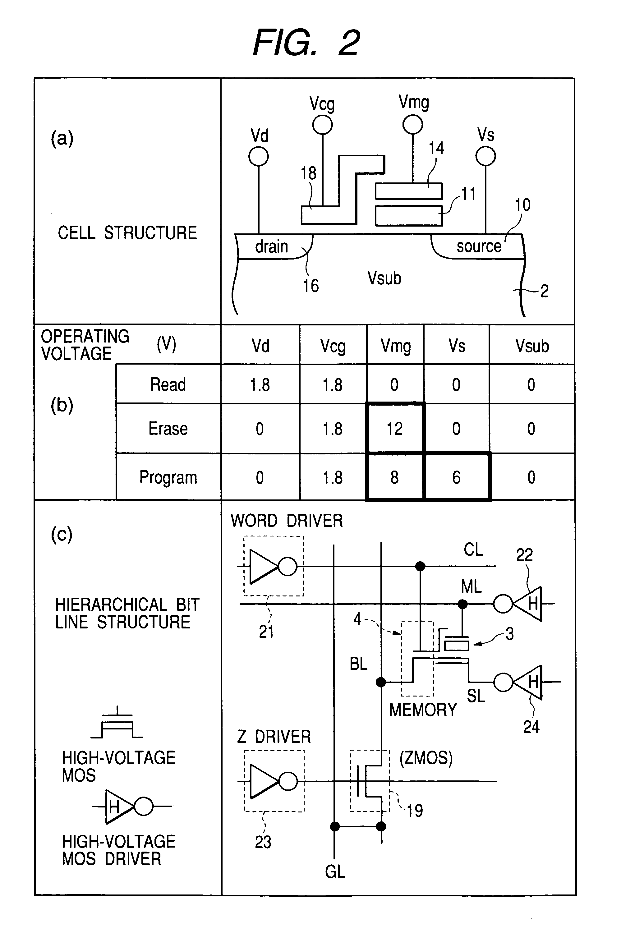
The present invention relates to a semiconductor device with nonvolatile memory cells. The invention provides a semiconductor device with a high-speed read operation and a low gate withstand voltage for the second transistor section of the nonvolatile memory cell. The second transistor section is thinner and has a lower gate withstand voltage than the first transistor section. The invention also includes a divided bit line structure and a switch MOS transistor for reducing parasitic capacity and speeding up the read operation. The invention further includes a first driver, a second driver, a third driver, and a fourth driver for controlling the control gate control line, the memory gate control line, the switch MOS transistor, and the source line, respectively.

Problems solved by technology

If nothing is done, then the split gate type memory cell is not fit for a high-speed operation under a low voltage.
Further, although Japanese Unexamined Patent Publication No.
However, it has been found out by the present inventors that there is a fear that where it is necessary to apply a high voltage even to a bit line upon writing as in the stack gate type memory cell, a MOS transistor for selectively connecting a sub bit line to its corresponding main bit line must be brought to high withstanding, whereby Gm of a read path is further reduced and the speeding up by a hierarchized bit line structure based on the main / sub bit lines will not function sufficiently.

Method used


Image

  • Nonvolatile semiconductor memory device employing transistors having different gate withstand voltages for enhanced reading speed
  • Nonvolatile semiconductor memory device employing transistors having different gate withstand voltages for enhanced reading speed
  • Nonvolatile semiconductor memory device employing transistors having different gate withstand voltages for enhanced reading speed

Examples


first embodiment

[0161]FIG. 40 is a cross-sectional view showing the present invention, which is illustrative of a memory cell using a floating gate. The memory cell comprises a p type well region PWEL provided over a silicon substrate, an n type diffusion layer MS which serves as a source region, an n type diffusion layer MD which serves as a drain region, a floating gate FLG, a tunnel oxide film FTO, an interlayer insulating film INTP, a memory gate electrode MG (material: n type polysilicon) for applying a high voltage upon writing / erasure, an oxide film CAP for protection of the memory gate electrode MG, a gate oxide film STOX for a selection MOS type transistor, a selection gate electrode SG made of n type polysilicon, and an insulating film GAPOX for insulating the selection gate electrode SG and the memory gate electrode MG. The gate oxide film STOX is characterized in that the thickness of the gate oxide film STOX is fabricated thinner than that of the insulating film GAPOX and that of a hig...

second embodiment

[0168]FIG. 43 is a cross-sectional view showing a second embodiment where the present invention is applied to a MONOS type memory cell that performs discrete charge storage. FIG. 43 is different from FIG. 40 in that a laminated structure is configured wherein the charge storage region results in a nitride film SIN of silicon, an oxide film BOTOX is formed just below the nitride film SIN, and an oxide film TOPOX is formed just above the oxide film BOTOX. The thickness of the nitride film SIN is set to less than or equal to 50 nanometers. Assuming that the thickness of the oxide film TOPOX is defined as tT and the thickness of the oxide film BOTOX is defined as tB, both tT and tB are set so as to reach a relationship of tB>tT where stored charges are pull out via the oxide TOPOX, whereas both tT and tB are set so as to reach a relationship of tB<tT where the stored charges are pulled out via the oxide film BOTOX. The relationship of the film thickness described in FIG. 42, i.e., tL≦tS...

third embodiment

[0174]FIG. 47 is a cross-sectional view showing a third embodiment where the present invention is applied to a memory cell using fine particles as a charge storage portion. Fine particles DOTS are provided on an underbedding oxide film BOTOX. As the material of each fine particle DOTS, may be mentioned polysilicon. Another material may be used. The diameter of the particle may preferably be 10 nanometers or less. An interlayer insulating film INTOX is deposited so as to cover up the fine particles DOTS, and a memory gate electrode MG is mounted just thereabove. The charge storage portion may be considered to be equal to a charge storage film having a trap property in that it becomes discrete. Accordingly, the contents of the present invention described up to now can be applied in any combination thereof or all combination thereof.

[0175]The relationship of tL≦tS<tH and the cell structure corresponding to the gist of the present invention have been described above. A specific manufact...


PUM


Abstract

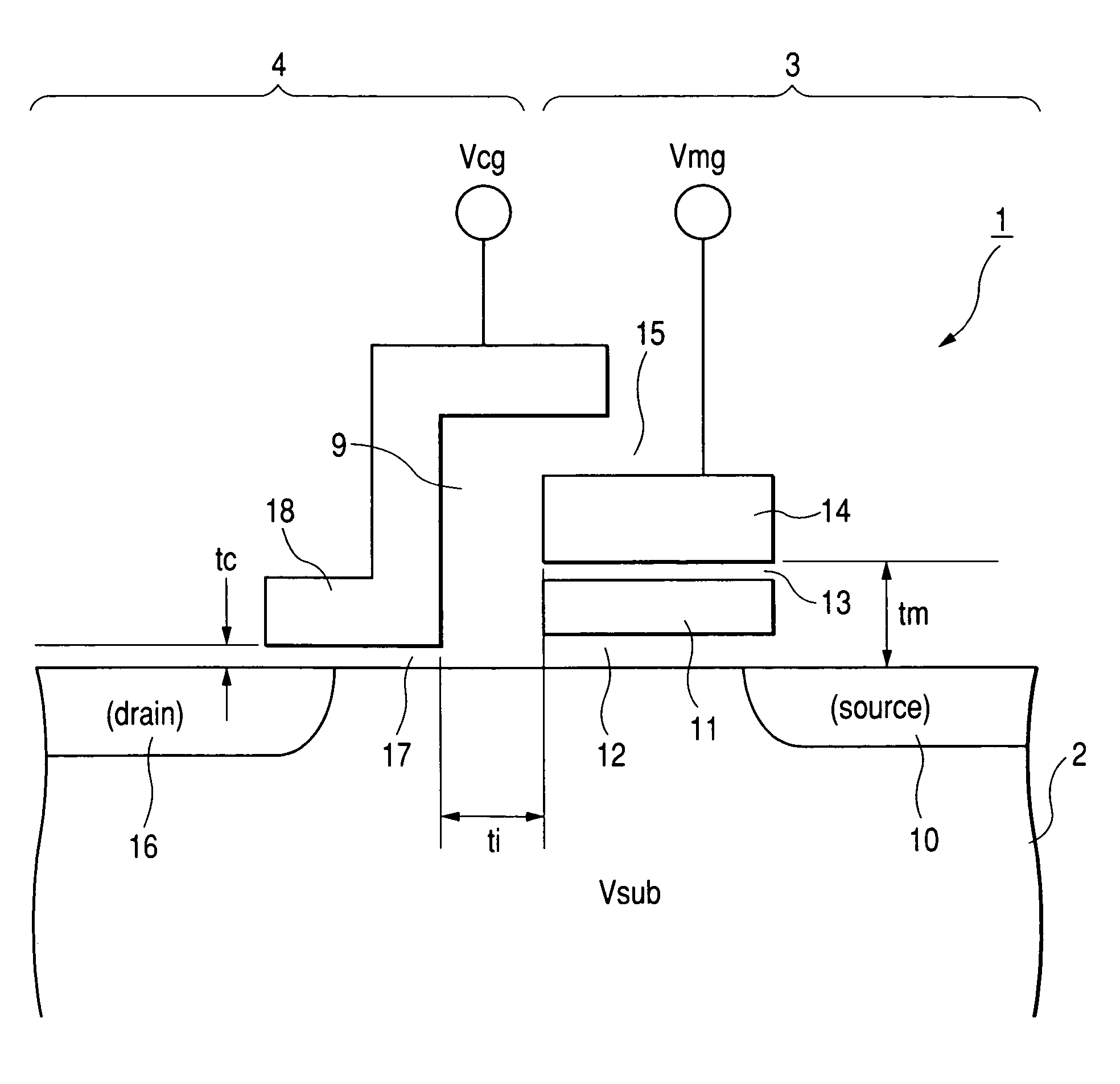
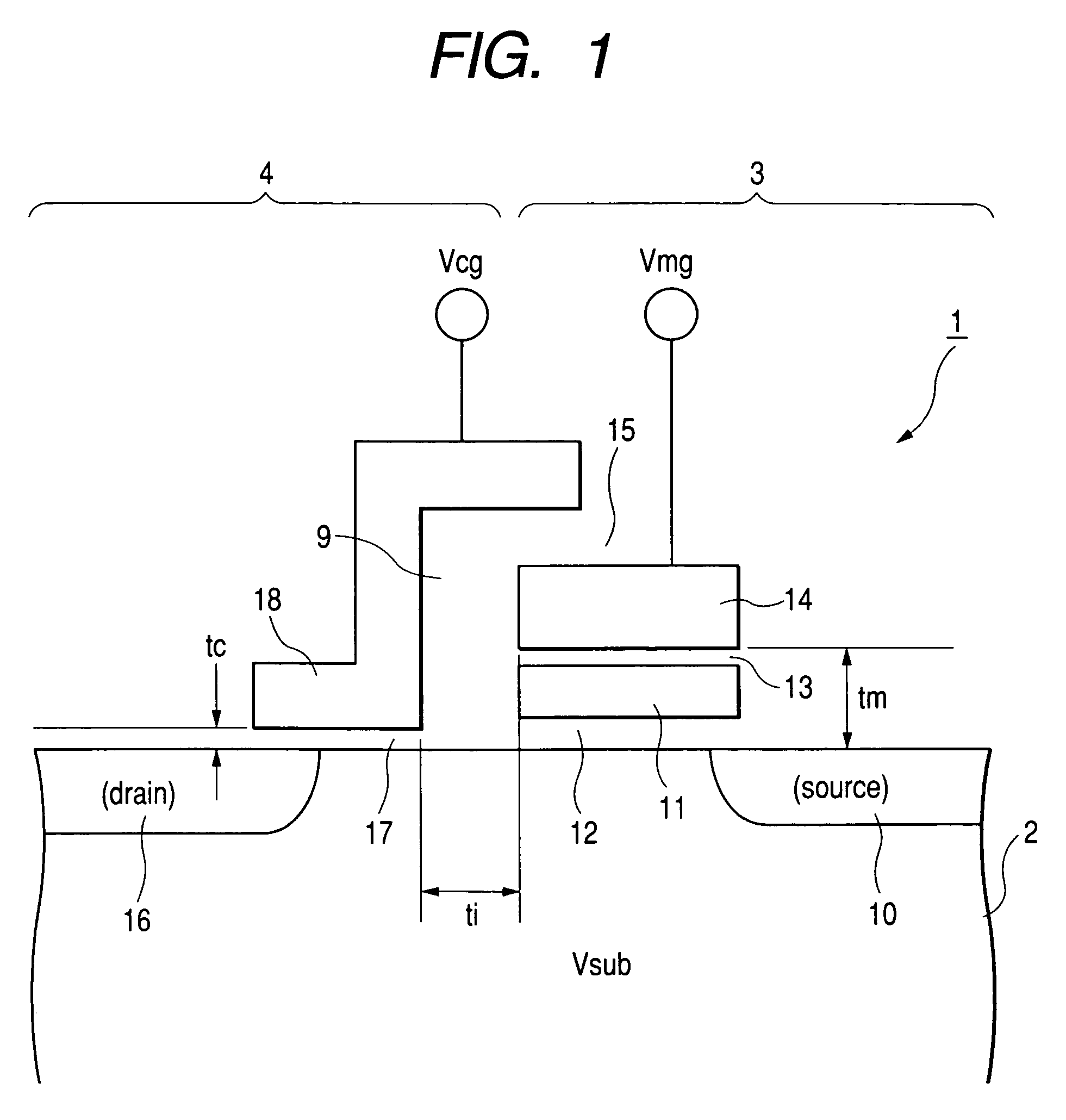
A semiconductor device includes a plurality of nonvolatile memory cells (1). Each of the nonvolatile memory cells comprises a MOS type first transistor section (3) used for information storage, and a MOS type second transistor section (4) which selects the first transistor section. The second transistor section has a bit line electrode (16) connected to a bit line, and a control gate electrode (18) connected to a control gate control line. The first transistor section has a source line electrode (10) connected to a source line, a memory gate electrode (14) connected to a memory gate control line, and a charge storage region (11) disposed directly below the memory gate electrode. A gate withstand voltage of the second transistor section is lower than that of the first transistor section. Assuming that the thickness of a gate insulating film of the second transistor section is defined as tc and the thickness of a gate insulating film of the first transistor section is defined as tm, they have a relationship of tc<tm.

Description

TECHNICAL FIELD[0001]The present invention relates to a semiconductor device having a nonvolatile memory, and particularly to a technology for reading memory information at high speed, e.g., a technology effective if applied to a flash memory or a microcomputer or the like including the flash memory provided on-chip.BACKGROUND ART[0002]As nonvolatile memory cells, may be mentioned, a split gate type memory cell and a stack gate type memory cell. The split gate type memory cell comprises two transistors of a memory MOS type transistor that constitutes a memory section, and a selection MOS type transistor for selecting its memory section to thereby fetch information therefrom. As a known document, there is known a technology described in 1994-Proceedings of IEEE, VLSI, Technology Symposium, pp 71–72. A structure and operation of a memory cell described therein will be explained in brief. This split gate type memory cell comprises a source, a drain, a floating gate and a control gate. ...

Claims


Application Information

Patent Timeline
Patent Type & Authority Patents(United States)
IPC IPC(8): H01L29/788H10B69/00G11C16/04H01L21/28H01L21/336H01L21/8247H01L29/423H01L29/78H01L29/792H10B41/30H10B41/40H10B41/49
CPCG11C16/26H01L21/28273H01L27/105H01L27/115H01L27/11521H01L27/11526H01L27/11546H01L29/42328H01L29/42332H01L29/4234H01L29/66825H01L29/7885H01L29/792G11C16/24G11C16/0433G11C16/0425G11C5/025G11C8/08G11C16/08G11C16/30H01L29/40114H10B69/00H10B41/30H10B41/40H10B41/49H01L29/788G11C16/04H01L21/28
Inventor TANAKA, TOSHIHIROUMEMOTO, YUKIKOHIRAKI, MITSURUSHINAGAWA, YUTAKAFUJITO, MASAMICHISUZUKAWA, KAZUFUMITANIKAWA, HIROYUKIYAMAKI, TAKASHIKAMIGAKI, YOSHIAKIMINAMI, SHINICHIKATAYAMA, KOZOMATSUZAKI, NOZOMU
Owner RENESAS ELECTRONICS CORP
Learn More