Method and apparatus for replacement of underground pipe

a technology for underground pipes and methods, applied in shaft equipment, manufacturing tools, portable drilling machines, etc., to achieve the effect of reducing the operation of the impactor and lessening the impact for

Inactive Publication Date: 2006-06-06
EARTH TOOL L L C
View PDF22 Cites 5 Cited by
  • Summary
  • Abstract
  • Description
  • Claims
  • Application Information

AI Technical Summary

Benefits of technology

[0031](e) reducing operation of the impactor between cyclic pulling strokes so that the impactor does not substantially move between strokes. “Reducing” in this context means lessening the impact force delivered by the striker to the bursti...

Problems solved by technology

Pressure fluid in the rear pressure chamber causes a forward stroke of the striker resulting in an impact ag...

Method used


Image

  • Method and apparatus for replacement of underground pipe
  • Method and apparatus for replacement of underground pipe
  • Method and apparatus for replacement of underground pipe

Examples


Embodiment Construction

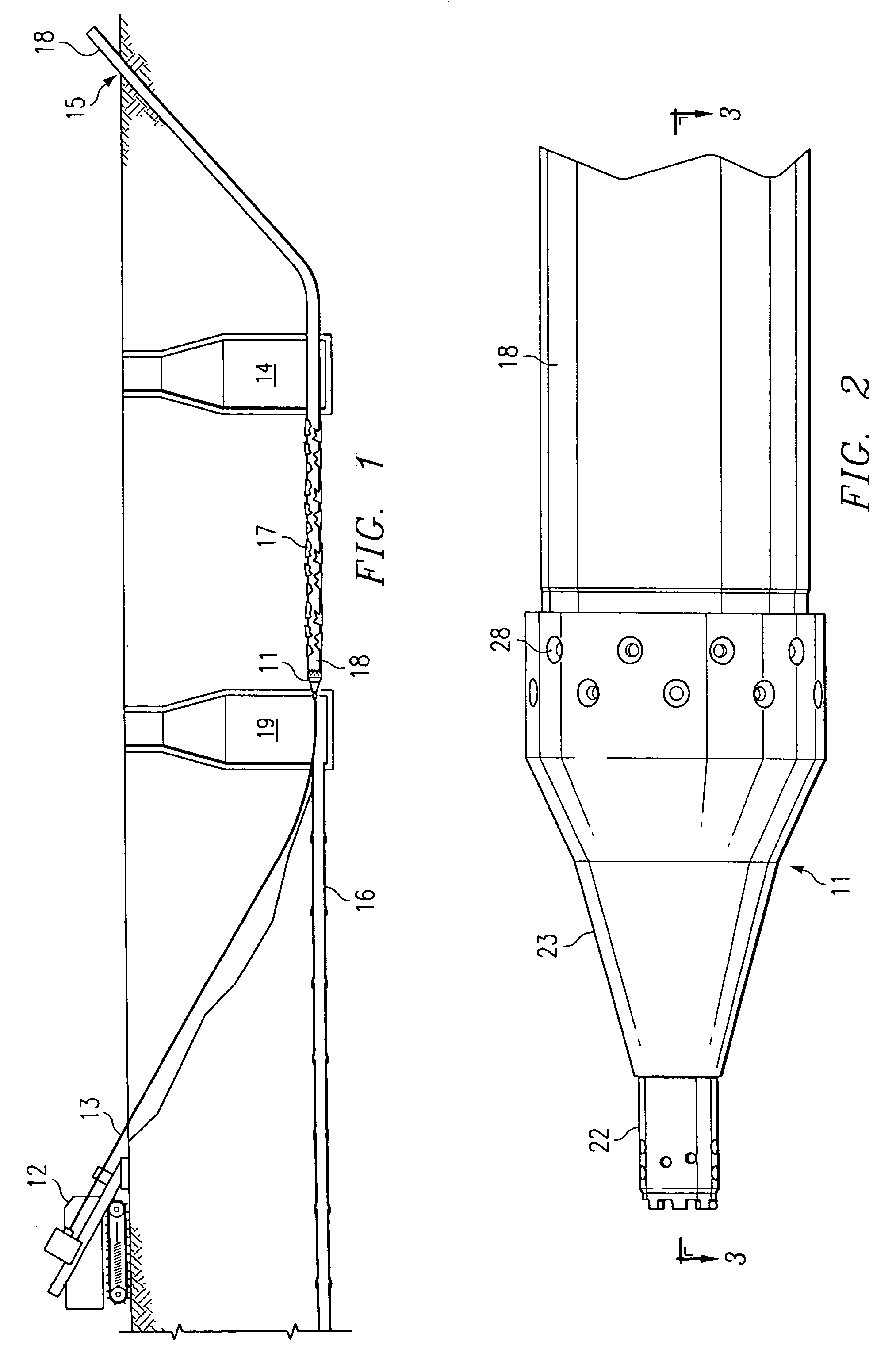
[0061]Referring to FIG. 1, a pipe bursting and replacement system 10 according to the invention includes an impactor 11 pulled by a directional drilling machine 12 by means of a drill string 13. Impactor 11 is positioned at a starting location, such as a manhole or entrance pit 14, and pulled through an existing pipeline 16, bursting it into fragments 17 which remain in the ground. The replacement pipe 18 is drawn along behind impactor 11 and occupies the same space as the existing pipeline.

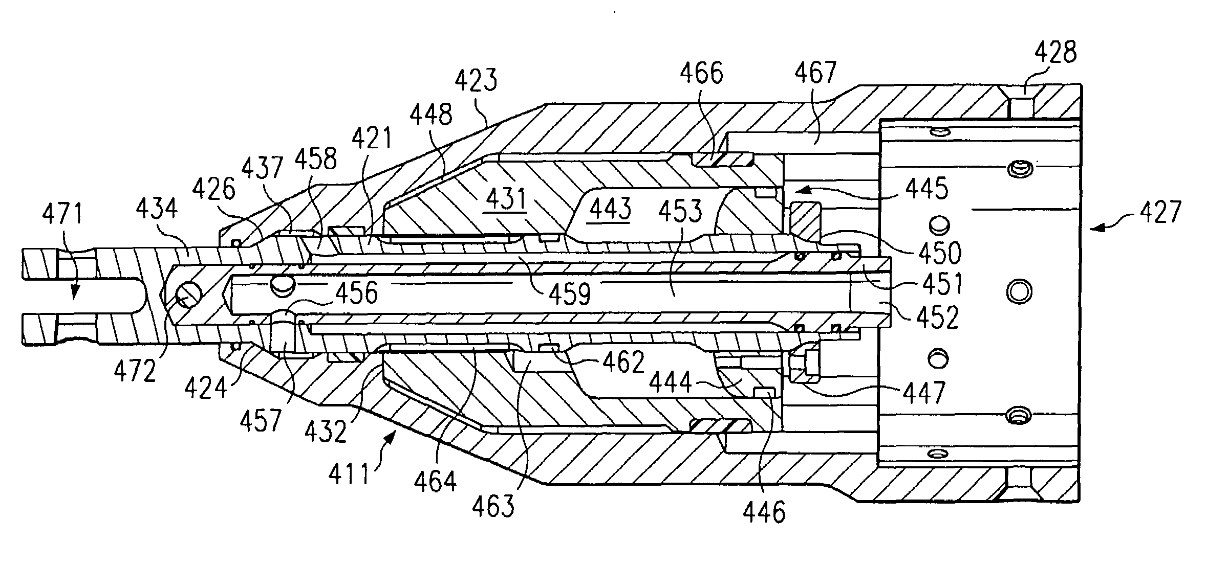
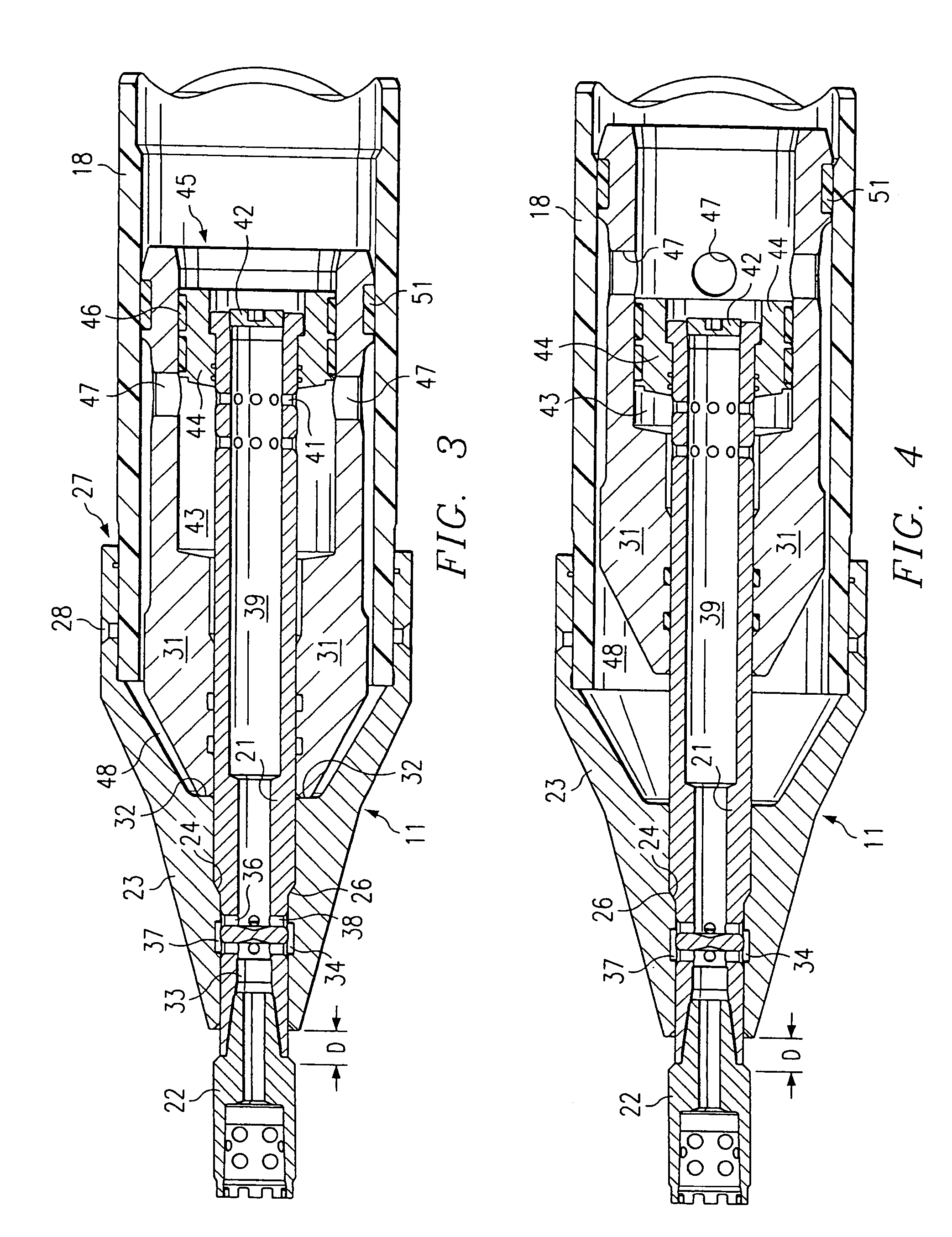
[0062]Impactor 11 as shown in FIGS. 2–5 includes an impact mechanism that aids in boring through the ground or bursting an existing pipe. Impactor 11 includes a central air inlet tube 21 that may be connected either directly or by means of an adapter 22 to the terminal end of drill string 13. A conical shell or bursting head 23 is mounted on the outside of tube 21 in close sliding contact therewith. A shoulder 24 leading to an enlarged outer diameter rear portion of tube 21 engages a slanted step...


PUM

PropertyMeasurementUnit
Forceaaaaaaaaaa
Pressureaaaaaaaaaa
Flexibilityaaaaaaaaaa

Abstract

An impactor for use with a directional boring machine for replacement of underground pipes includes a bursting head having a rearwardly opening recess and a front end opening that communicates with the recess. An inlet pipe is connected at its front end to a distal end of the drill string and extends into the recess of the bursting head through the front end opening. A striker is mounted for sliding movement along the inlet pipe, and a distributing mechanism responsive to pressure fluid supplied through the drill string and inlet pipe causes the striker to reciprocate in the rearwardly opening recess of the head to deliver forward impacts against the bursting head. The striker and distributing mechanism are mounted in a tubular housing, and a pulling connection is provided by which the impactor can be pulled by the drill string while the striker is delivering impacts against the head in the same direction as a pulling force exerted by the drill string. The bursting head is preferably slidably mounted on the inlet pipe and moves forward relative to the inlet pipe and drill string in response to an impact of the striker against the bursting head. The impactor can be readily used with existing directional boring machines.

Description

[0001]This application is a division of U.S. Ser. No. 09 / 946,081, filed Sep. 4, 2001, U.S. Pat. No. 6,761,507, issued Jul. 13, 2004.TECHNICAL FIELD[0002]This invention relates to systems for underground pipe bursting and replacement.BACKGROUND OF THE INVENTION[0003]A variety of systems are now known for the installation of underground pipes, particularly for the replacement of an existing deteriorated pipe. Pneumatic impact tools that bore horizontal holes or burst existing pipelines are in widespread use. See, for example, Wentworth et al. U.S. Pat. No. 5,025,868. In one widely practiced method, a pneumatic impact boring tool is sent through the existing pipeline such that the head of the tool, which may be provided with blades that apply intense local pressure to the existing pipe, fractures or splits the existing pipe. See, for example, Streatfield et. al. U.S. Pat. Nos. 4,720,211, 4,738,565 and 4,505,302. A replacement pipe, typically made of plastic such as HDPE, is drawn along...

Claims


Application Information

Patent Timeline
IPC IPC(8): B25D9/04E21B4/14E21B7/30E21B17/05F16L55/165
CPCE21B4/14F16L55/1658E21B17/05E21B7/30
Inventor WENTWORTH, STEVEN W.RANDA, MARK D.
Owner EARTH TOOL L L C
Why Eureka
Try Eureka