
Seasoning system and method

a technology of seasoning system and method, which is applied in the field of equipment and techniques for seasoning snack foods, can solve the problems of difficult to correctly use equipment, insufficient seasoning evenly distributed over the product area, and insufficient seasoning, etc., and achieves the effects of convenient and convenient use, improved seasoning coverage, and improved seasoning

Inactive Publication Date: 2006-06-06
SVEJKOVSKY PAUL A
View PDF1 Cites 16 Cited by
  • Summary
  • Abstract
  • Description
  • Claims
  • Application Information

AI Technical Summary

Benefits of technology

The system achieves superior seasoning coverage, reduces product breakage, and maintains high sanitation conditions, ensuring consistent product quality and cost savings by accurately matching seasoning to product volume, regardless of density variations.

Problems solved by technology

There are numerous problems that exist with current equipment and techniques for seasoning snack foods.
As a primary example, existing equipment and techniques do not correctly match the desired amount of seasoning added to the incoming product flow.
Since the weight of the seasoning may not be insignificant to the weight of the overall product, and since seasoning is recognized as either the most expensive raw ingredient or one of the most expensive raw ingredients in most snack food products, the over-application of seasoning by a producer or the loss of business based upon under-seasoning represents millions of dollars each year to the food processing industry.
Another problem with seasoning systems is that the seasoning is not evenly dispersed over the area of the product.
It is also difficult to correctly use this equipment so that the seasoning is dispersed over the entire area of the incoming product.
Continued problems with the application of seasoning using the above auger have led to the use of a vibratory conveyor tray with a bias cut discharge to apply the seasoning.
This solution, however, creates new problems since the vibratory conveyor that moves the incoming product is the motion that moves the seasoning on the scarf plate.
Varying product density has a significant effect on the travel rate of a product being moved with a vibratory conveyor, and accordingly the time shift between the measurement of the base product and the application of seasoning to that measured product causes a mismatch between the seasoning and the base product.
Moreover, vibratory conveyors tend to develop a build-up of seasoning over time and therefore have sanitation problems or flow problems due to uneven dispersion.
This separate drive mechanism for the scarf plate increases the cost, weight, and complexity of the seasoning system, and also prevents the system from being easily cleaned, particularly during seasoning change operations.
While these tumbler drums effectively mix the base product and the seasoning, current drum technology also causes undesirably high product breakage.
If the seasoning and oil spray operations were performed in the same tumbler, cleaning the tumbler becomes very difficult because seasoning and oil tend to cake in the drum.
Accordingly, an upstream tumble drum for mixing the product with the oil and a downstream tumble drum for mixing the oiled product with the seasoning has been used, although this again increases equipment costs.
The addition of this second tumble drum to a product line may thus adversely affect the height of the product as it moves through the food processing system.
Also, the addition of another piece of equipment to an existing system may create problems with the increased product travel length of the new system.
Finally, and perhaps most importantly, significant problems exist between the seasoning system and downstream equipment, such as scale and bagging equipment.
Generally, the food processing industry does not utilize systems which provide for real time monitoring of activities and changes to the operation of the food handling mechanisms to optimize the system.
Since the prior art conventionally uses only a feedback system, however, neither the upstream seasoning system nor the distribution system achieves the proper flow of product to the downstream scale or bagger.

Method used


Image

  • Seasoning system and method
  • Seasoning system and method
  • Seasoning system and method

Examples


Embodiment Construction

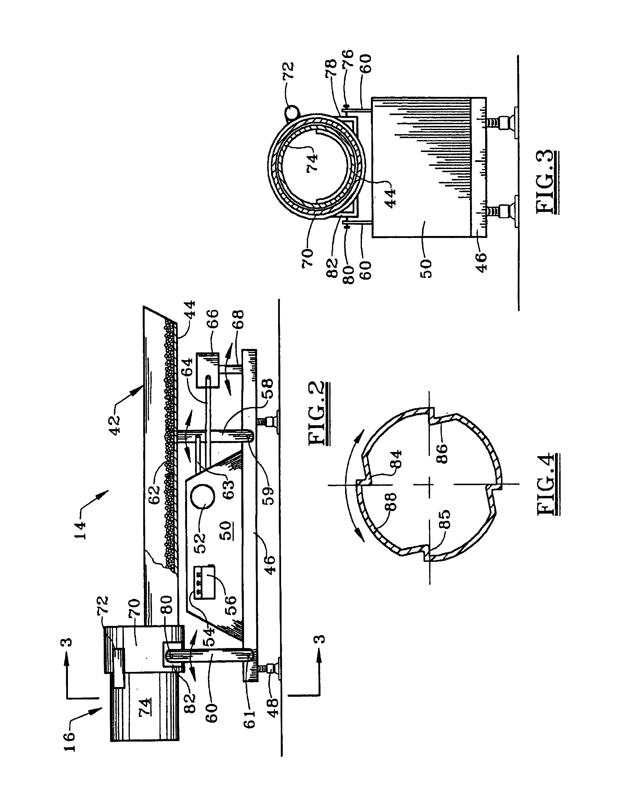
[0044]As explained subsequently, FIGS. 1-5 disclose one embodiment of a system according to the present invention, and FIG. 6 discloses another embodiment of the present invention. The preferred seasoning distribution pan as shown in FIG. 7 may be used in either embodiment.

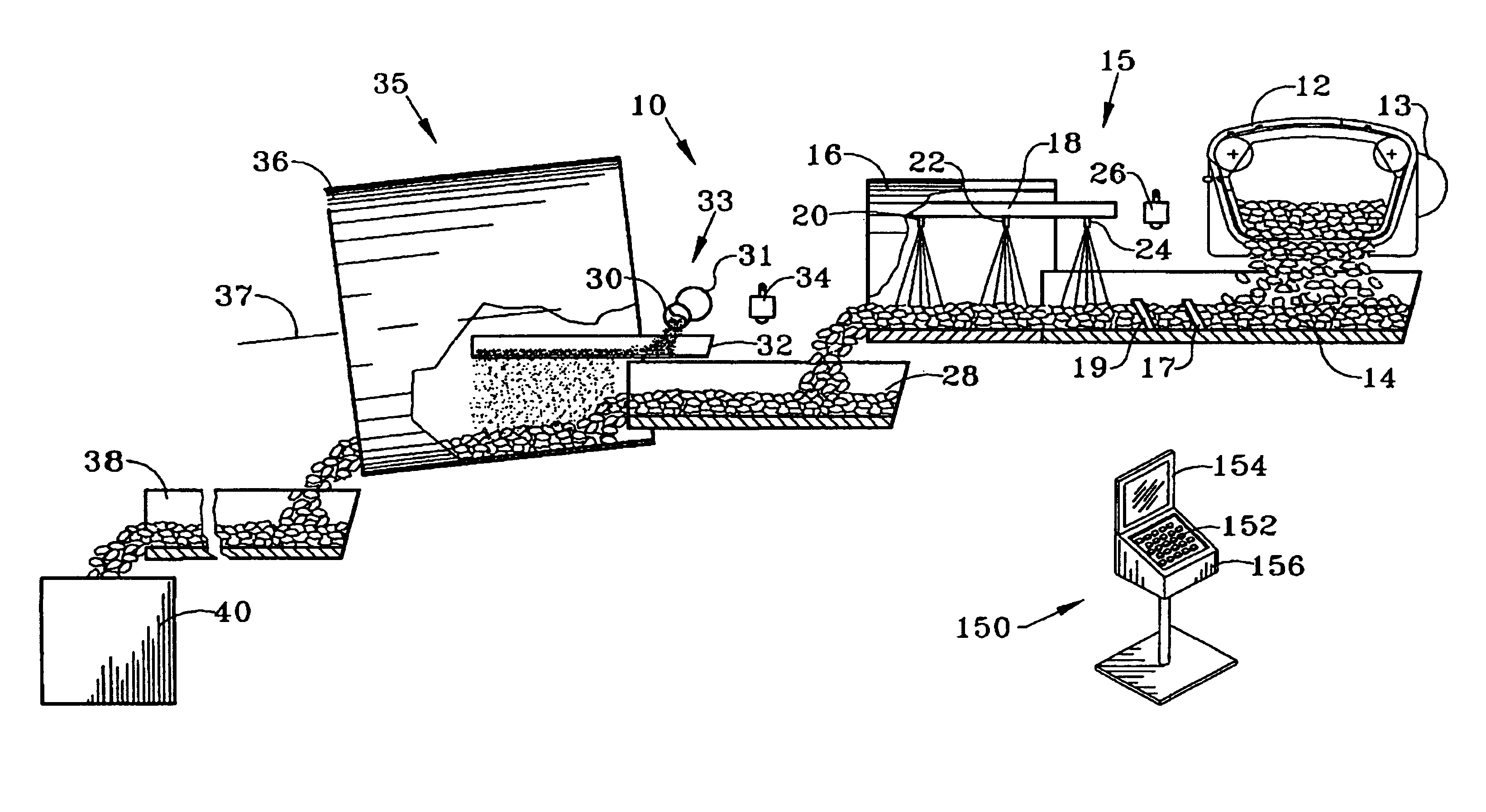
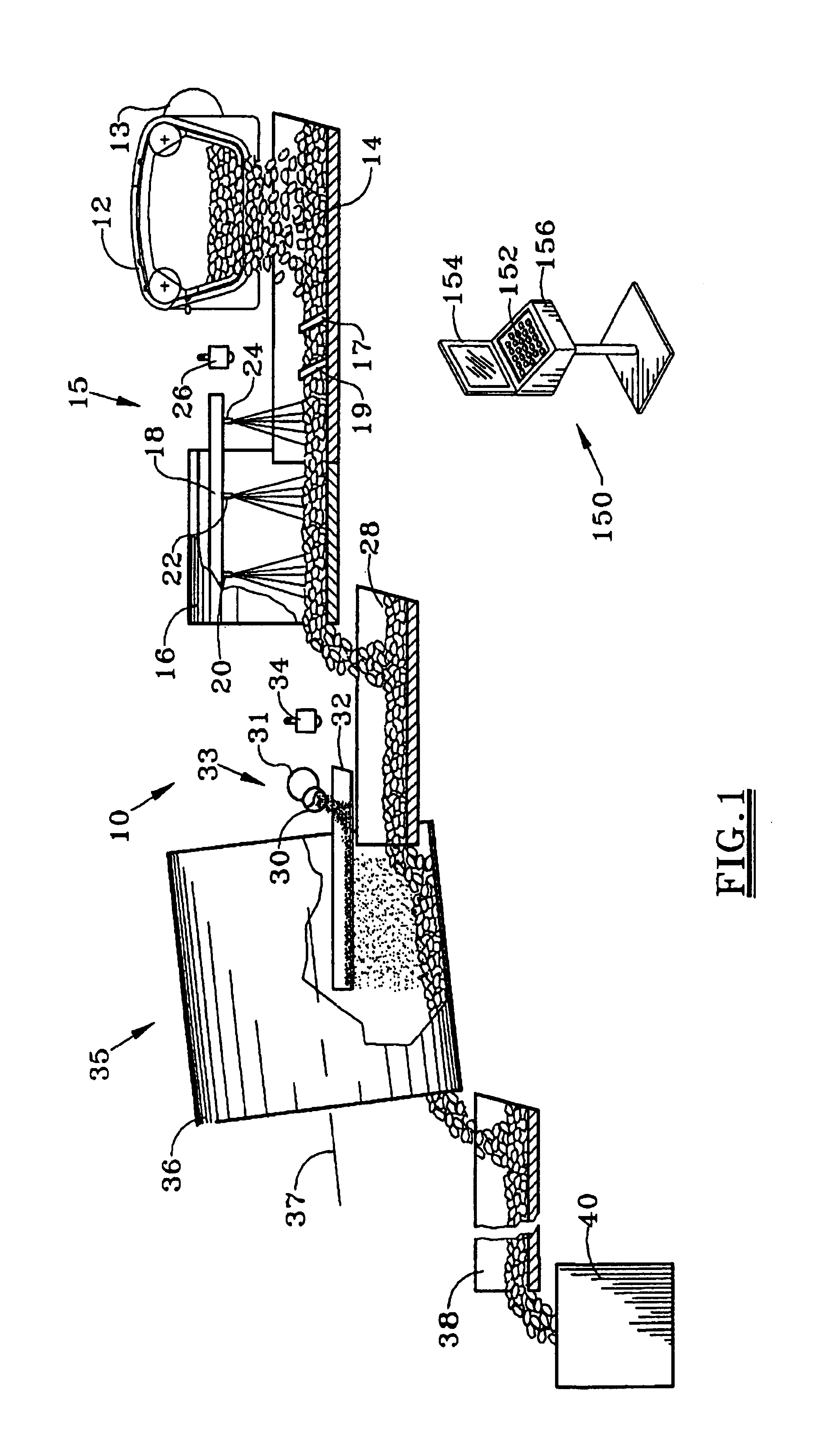
[0045]FIG. 1 simplistically depicts one seasoning system 10 of the present invention which is particularly well suited for food product seasoning applications wherein the product throughput is relatively high. Existing seasoning systems are capable of handling several thousand pounds of incoming food product per hour, and even higher product throughput rates for future equipment are likely.

[0046]The seasoning system 10 starts with product incoming to the seasoning system having the product flow rate regulated by a separate conveyor or a proportional gate such as the gate mechanism 12 generally shown in FIG. 1. Other proportional gate mechanisms or conventional gate mechanisms may be used to control the product flo...


PUM


Abstract

An improved seasoning system 10, 11, 13 uniformly coats a food product with the desired amount of seasoning, with the seasoning rate preferably being controlled as a function of the product volume signals from the sensors 26, 34, 108 and 110. The seasoning system preferably utilizes linear motion conveyors and either a rotating drum 36 or a deflector 98 and a second seasoning unit 112, 114 between linear conveyors 94, 96. Oil may be sprayed onto food products and tumbled in a drum 16 which both rotates and moves in a reciprocating manner with the conveyor tray 14. An improved seasoning tray 123, 144, 148 has a planar floor 122, 138, 162 with an angled discharge edge 124, 137, 182 for uniformly distributing seasoning on the product. The seasoning system minimizes damage to the food product and uniformly coats the product with a desired amount of seasoning.

Description

[0001]This application is a continuation of U.S. application Ser. No. 09 / 757,177 filed Jan. 9, 2001, now abandoned, which is a continuation in part of U.S. application Ser. No. 09 / 641,190 filed Aug. 17, 2000, now U.S. Pat. No. 6,588,363.FIELD OF THE INVENTION[0002]The present invention relates to equipment and techniques for seasoning snack foods, such as chips, in a food processing facility. More particularly, this invention relates to significant improvements which evenly and consistently coat the product with seasoning, thereby reducing the amount of seasoning used and / or increasing the customer's desire for the snack food product.BACKGROUND OF THE INVENTION[0003]The food processing industry has long recognized the desirability of seasoning snack foods, such as potato chips, in a consistent and even manner. This industry has thus recognized that significant cost savings and increased customer satisfaction can be obtained when each chip from a bag of potato chips is consistently a...

Claims


Application Information

Patent Timeline
Patent Type & Authority Patents(United States)
IPC IPC(8): B05C19/06A23P1/08
CPCA23P1/082A23P1/085A23P1/083A23P20/12A23P20/13A23P20/15A23P20/18
Inventor BURKE, DAVID L.FITZGERALD, JONNYKNODELL, JR., THOMAS G.PETRI, KENNETH C.SVEJKOVSKY, P. BLAKESVEJKOVSKY, PAUL A.
Owner SVEJKOVSKY PAUL A
Learn More