
Method for controlling a blister packaging machine

a packaging machine and control method technology, applied in the direction of packaging, wrappers, shrinkage wrappers, etc., can solve the problems of reducing the efficiency of the packaging system, affecting the speed of product supply in the blister packaging machine, and affecting the efficiency of the entire packaging system

Inactive Publication Date: 2006-06-06
IWK VERPACKUNGSTECHN
View PDF16 Cites 21 Cited by
  • Summary
  • Abstract
  • Description
  • Claims
  • Application Information

AI Technical Summary

Benefits of technology

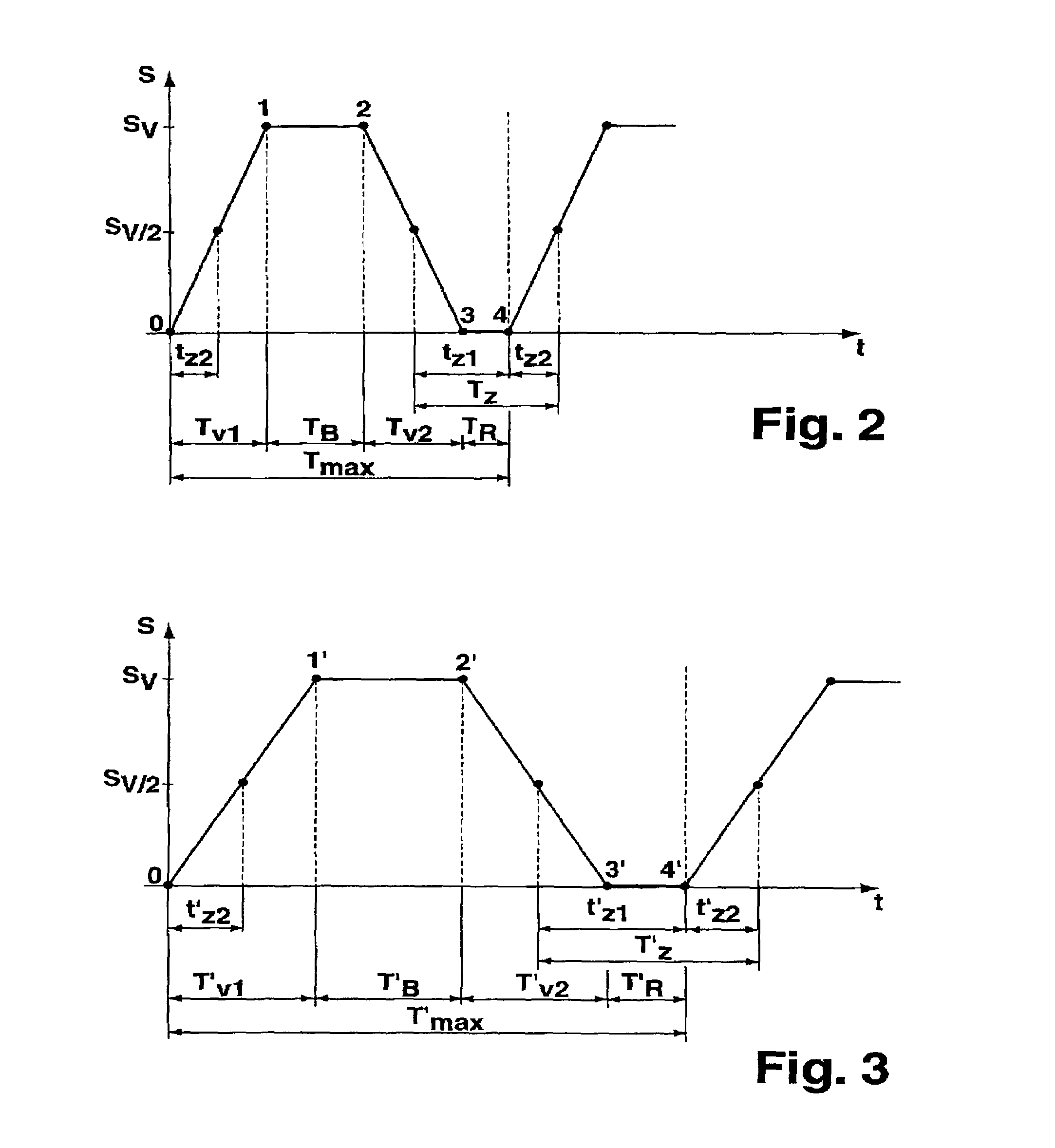
[0019]The work station whose cycle curve changes when the cycle rate is changed may be a forming station of a blister packaging machine. The forming station has two forming plates which can be adjusted relative to each other and between which a bottom sheet having cup-shaped receptacles is provided. If the bottom sheet is made from plastic material, it is processed in a pre-heated state and cooled in the forming station. The first adjustment motion is then provided by the closing motion of the forming plates, wherein the closing motion is terminated only when the final position of the forming plates has been reached, and the forming plates may already abut in the last motional phase of the closing motion. At the end of the closing motion, the forming plates remain in a treatment state for a time period TB, in which the bottom sheet is shaped and optionally cooled. The second adjusting motion is the opening motion of the forming plates which return into their initial open position. The forming plates subsequently remain in their open position for a time period TR. If the cycle time difference ΔT, obtained through reduction of the cycle rate is used completely to change the duration TR of the resting state and the temperature of the pre-heated sheet remains the same, the actual treatment of the bottom sheet in the forming station of the blister packaging machine does not change and the forming plates move at the preset speed. Reduction of the cycle rate merely causes the forming plates to remain in their open position for a longer period at the end of the cycle. Keeping the time periods TV1, TB and TV2 constant keeps the process-relevant parameter of the forming time constant thereby providing good shaping of the bottom sheet and at the same time providing high processing reliability.

Problems solved by technology

Practice has shown that operation of the blister packaging machine which is part of a larger packaging system can cause unexpected problems which reduce the efficiency of the packaging system.
These problems may be based on disturbances of individual stations of the blister packaging machine or also disturbances or problems in upstream or downstream systems, e.g. in a downstream cartoning machine.
Moreover, there could be cycle problems in downstream machines, e.g. in a bundle packer, or product tolerances which have a negative effect on the speed of product supply in the blister packaging machine.
In addition, there may be a shortage of staff for the entire packaging system due to illness and / or holidays, with the consequence that the processing speed thereof must be reduced.
Since the above-mentioned problems and disturbances cannot always be eliminated or counteracted immediately, operation of the blister packaging machine is conventionally continued either with an increased rejection rate or reduced packaging quality.
This measure could, however, change the forming and sealing parameters to such an extent that perfect forming and sealing processes are no longer guaranteed.
Problems in other machines of the packaging line could also require a reduction in the cycle rate.
Changing of the process parameters can cause erroneously or incompletely shaped cups.

Method used


Image

  • Method for controlling a blister packaging machine
  • Method for controlling a blister packaging machine
  • Method for controlling a blister packaging machine

Examples


Embodiment Construction

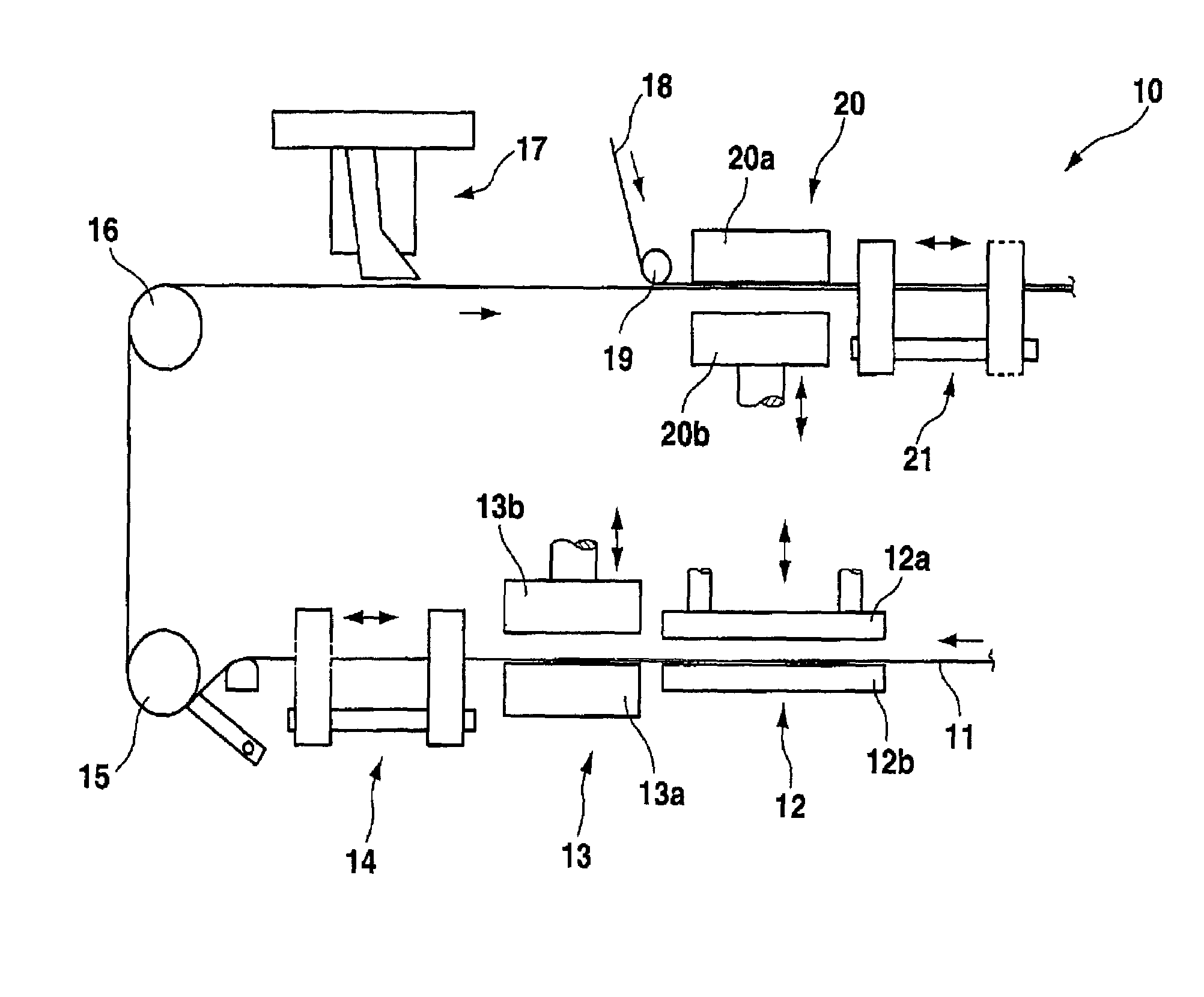
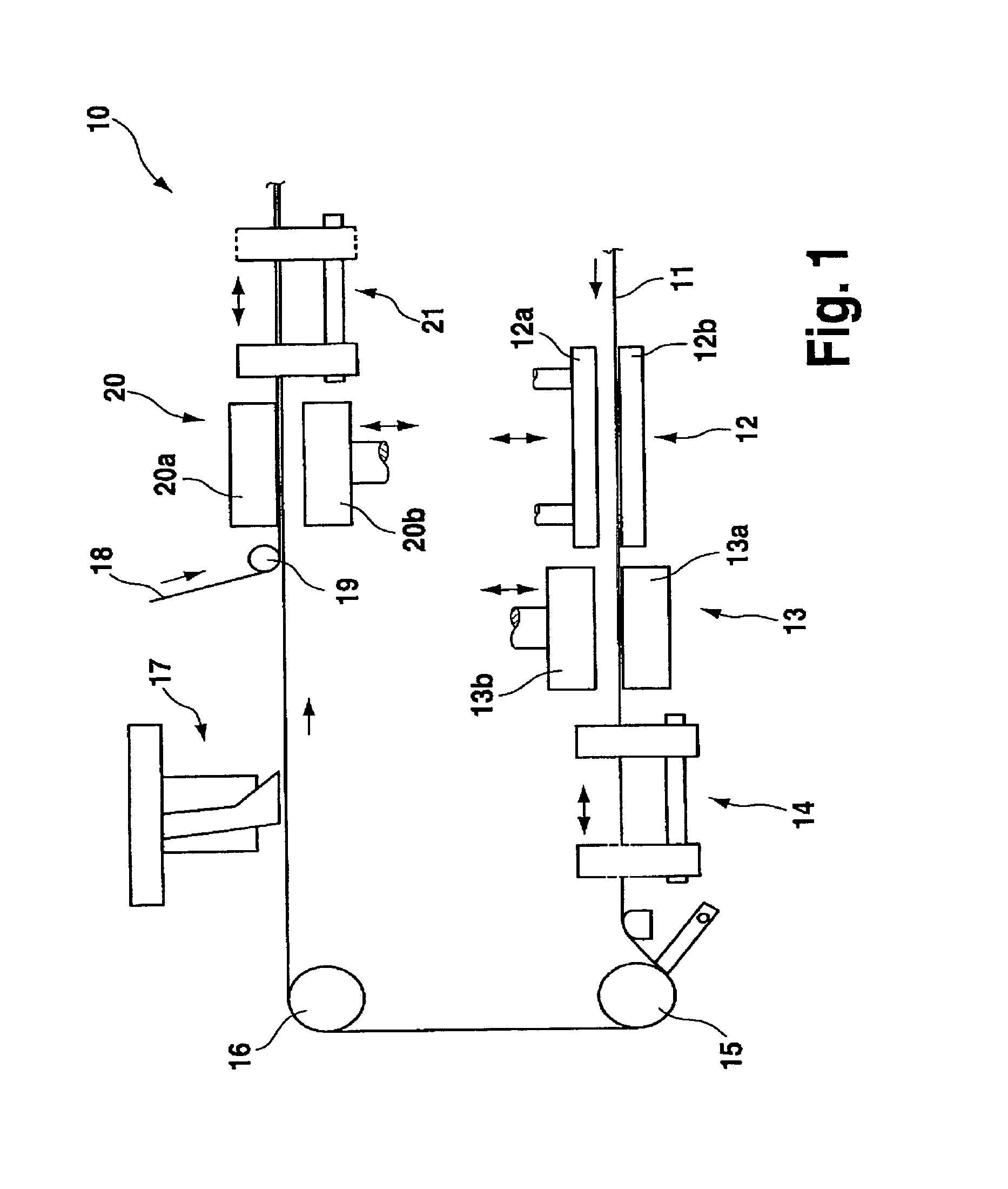
[0029]FIG. 1 schematically shows the essential components of a blister packaging machine 10. A plastic bottom sheet 11 is delivered by a supply and initially fed to a heating station 12 which comprises a lower heating plate 12b and an upper heating plate 12a which can be adjusted relative to the lower heating plate 12b. When the two heating plates 12a and 12b are closed, the bottom sheet received therebetween is heated.

[0030]A forming station 13 is directly adjacent to the heating station 12 and comprises a lower forming plate 13a and an upper forming plate 13b which can be adjusted relative thereto. The two forming plates 13a and 13b, which are shown in the open position, can be closed thereby cooling the bottom sheet which is received between the closed forming plates 13a and 13b and at the same time provided with cup-shaped depressions via a compressed air supply or forming dies. The forming station 13 is followed by a transport device 14 for pulling the bottom sheet 11 in cycles...


PUM

PropertyMeasurementUnit
Fractionaaaaaaaaaa
Fractionaaaaaaaaaa
Fractionaaaaaaaaaa

Abstract

A method for controlling a blister packaging machine has a work station which at least operates in cycles and which performs at least one first adjusting motion for a time period TV1 during one work cycle, followed by a treatment state for a time period TB, in which a product and / or material is treated. A second adjusting motion is then performed for a time period TV2 followed by a resting state for a time period TR. The time periods TV1, TB, TV2 and TR and a cycle rate R (=cycles / min) of the packaging machine are preset and at least the cycle rate R can be changed to a different cycle rate RV using an input device. A cycle time difference ΔT which results from the changed cycle rate RV is substantially used to change the duration TR of the resting state. The time periods TV1, TB and TV2 preferably remain unchanged when entering a different cycle rate RV.

Description

[0001]This application is the national stage of PCT / EP2004 / 000381 filed on Jan. 20, 2004 and also claims Paris Convention priority of DE 103 02 723.8 filed Jan. 23, 2003.BACKGROUND OF THE INVENTION[0002]The invention concerns a method for controlling a blister packaging machine having at least one work station which operates in cycles and performs at least one first adjusting motion for a time period TV1 during one work cycle, assumes a subsequent treatment state for a time period TB in which a product and / or material is / are treated, and performs a second adjusting motion for a time period TV2 which is optionally followed by a resting state for a time period TR, wherein the time periods TV1, TB, TV2 and TR and a resulting cycle rate R (=cycles / min) of the packaging machine are preset and at least the cycle rate R can be changed to a different cycle rate RV using an input means.[0003]A blister packaging machine of conventional structure comprises a forming station, in which a plurali...

Claims


Application Information

Patent Timeline
IPC IPC(8): B65B47/00B65B53/00B65B9/04B65B57/00B65B59/00
CPCB65B9/04B65B59/00B65B57/00B65B5/103B65B9/045B65B59/003
Inventor CHRIST, RICHARD
Owner IWK VERPACKUNGSTECHN
Learn More