
Method and system for suppressing ASE on a WDM network

a technology of optical communication network and suppression method, which is applied in the field of method and system for suppressing ase on an optical communication network, can solve the problems of generating noise (ase) over the entire spectrum of the oas bandwidth, and affecting the transmission path of the blocking filter. , to achieve the effect of eliminating signal amplitude instabilities and suppressing as

Active Publication Date: 2006-05-30
CIENA
View PDF6 Cites 22 Cited by
  • Summary
  • Abstract
  • Description
  • Claims
  • Application Information

AI Technical Summary

Benefits of technology

The invention relates to a method for improving the performance of a wavelength division multiplexed optical communication system by reducing signal amplitude instabilities and ASE (amplified spontaneous emission) noise. The technical effects of the invention include the use of optical amplifiers, banded optical add-drop multiplexers, a tunable edge filter, a fiber-optic ring network, and a wavelength assignment method that suppresses ASE on a WDM system. The invention also includes a wavelength decommissioning method for deassigning channels from a transmission path with an amplified transmission window. Overall, the invention enhances the stability and performance of optical communication systems.

Problems solved by technology

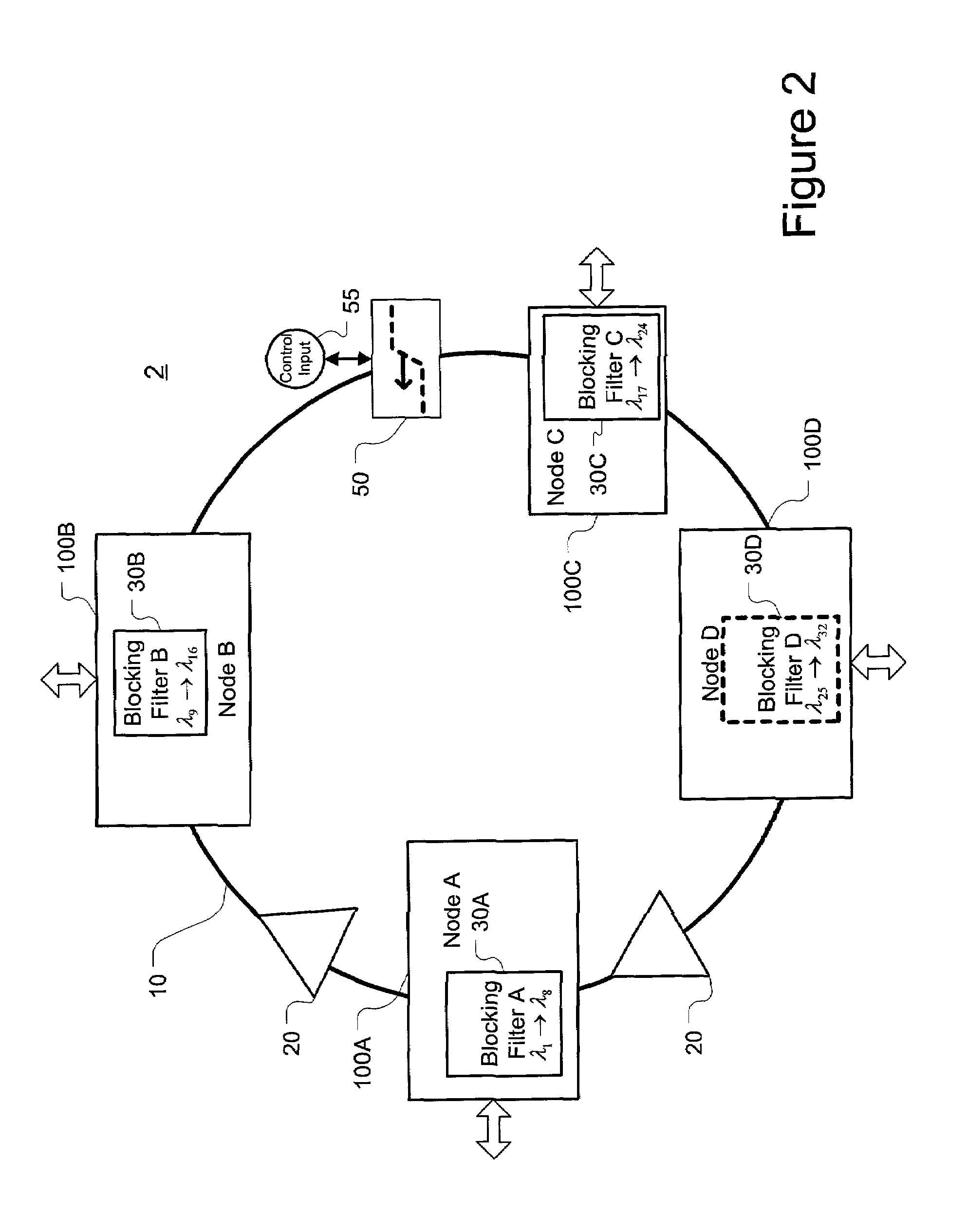
Such a blocking filter presents a large loss in the transmission path over its wavelength interval of interest (stop band), over and above the ring's fiber loss.
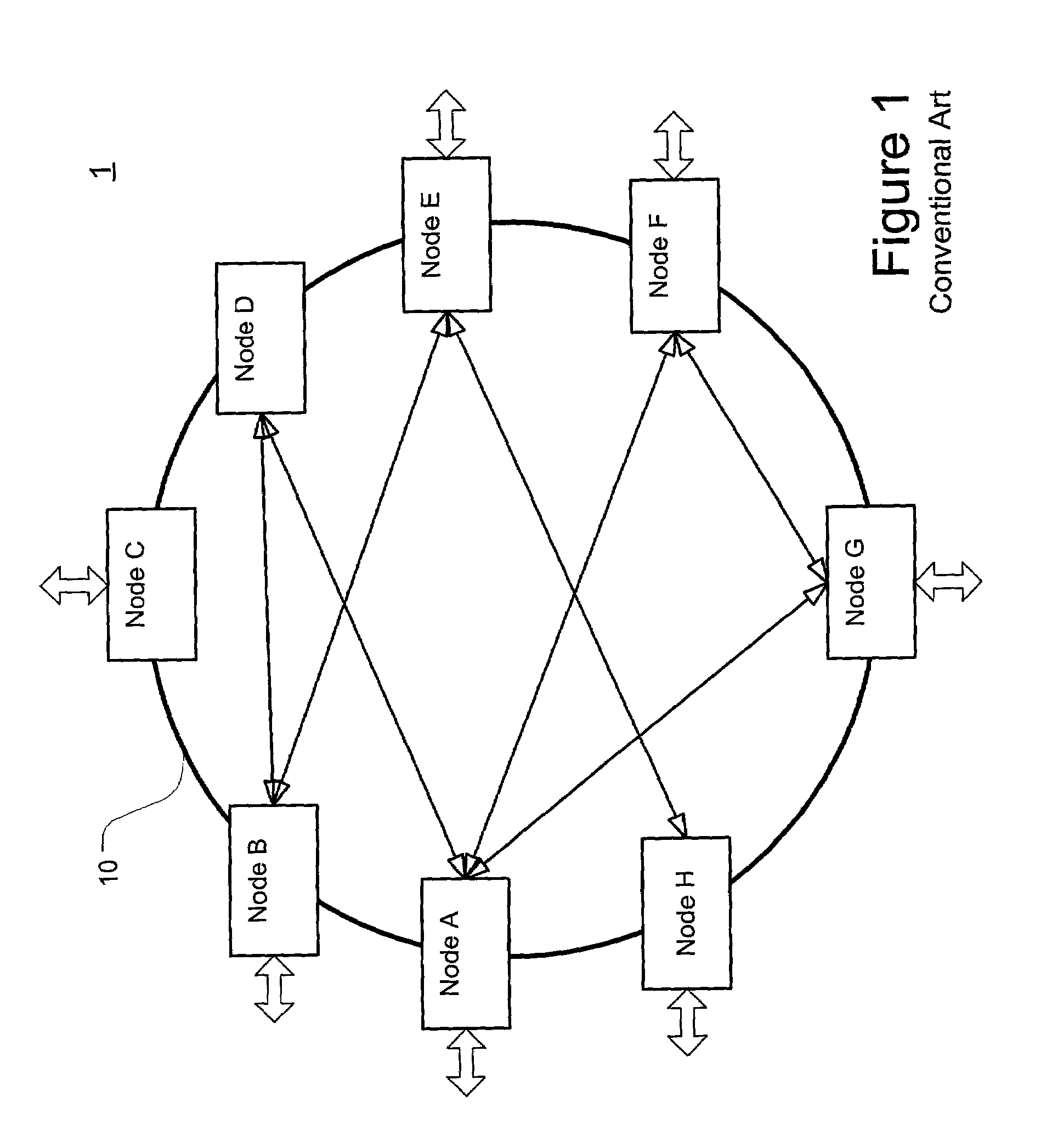
Unused wavelengths, however, may not have associated blocking filters deployed on the ring and so the ring's transmission loss at these wavelengths is the same as the fiber loss.
While OAs compensate for transmission loss by amplifying the signals present on the ring, they also generate noise (ASE) over the entire spectrum of the OAs bandwidth.
The ASE power that grows under such conditions may actually cause lasing, but more commonly, it simply creates power fluctuations for the signals carried on the ring.
These power instabilities may disrupt the useful signals' quality of transmission and are undesirable.

Method used


Image

  • Method and system for suppressing ASE on a WDM network
  • Method and system for suppressing ASE on a WDM network
  • Method and system for suppressing ASE on a WDM network

Examples


second embodiment

[0062]FIG. 9 illustrates the inventive WDM transmission system 3 including nodes A, B, C, and D (100A, 100B, 100C, and 100D) in which lengths of optical fiber 10 connect the nodes in a ring-based architecture. Many of the components are similar or identical to those shown in system 2 illustrated in FIG. 2 and described above in detail. Thus, only the differences will be explained further.

[0063]One such difference is the addition of a network manager 70. The network manager 70 may be based on conventional network management software applications that monitor and control WDM optical networks. An example of a system having such a network manager is shown in U.S. Pat. No. 6,163,392. In essential part, the network manager 70 is a software application adapted to the functionality of the invention, running on a conventional microprocessor based computer architecture and having the ability to communicate with the system 3.

[0064]Specifically, the network manager 70 may interface with a servi...

third embodiment

[0073]FIG. 13 illustrates the inventive WDM transmission system 4 including nodes A, B, C, and D (100A, 100B, 100C, and 100D) in which lengths of optical fiber 10 connect the nodes in a linear architecture. Many of the components are similar or identical to those shown in system 2 illustrated in FIG. 2 and described above in detail. Thus, only the differences will be explained further.

[0074]The linear WDM transmission system 4 shown in FIG. 13 may be part of a much larger network as indicated by the connection points 4 and 5. Like the ring systems 2 and 3, linear system 4 may be a “partially populated system” in which less that the total number of channel bands and corresponding blocking filters 30 are present. This is illustrated in FIG. 13 where the flocking filters 30C and 30D are shown in dotted lines indicating that it has not been installed or otherwise switched into the transmission path. Thus, the corresponding channel bands (e.g. λ27→λ24 and λ25→λ32) are not blocked and ASE...


PUM


Abstract

A method and apparatus for assigning channel bands to a wavelength division multiplexed (WDM) system is disclosed. The WDM system includes an arrangement of optical amplifiers, banded optical add-drop multiplexers (OADMs) having blocking filters, and a tunable edge filter. The channel band assignment method suppresses amplified stimulated emissions (ASE) in a partially populated system in which at least one of the blocking filters is not in the transmission path. Channel bands are assigned from one edge of an amplified transmission window to the other in a sequential order and the tunable edge filter is adjusted to attenuate ASE wavelengths not blocked by the blocking filters as channels are assigned. A channel decommissioning method is also disclosed which employs similar techniques and the tunable edge filter to suppress ASE as blocking filters are removed or otherwise deselected from the transmission path.

Description

BACKGROUND OF THE INVENTION[0001]1. Field of Invention[0002]The invention generally relates to a method and system for improving an optical communications network. More particularly, the invention relates to a method and system that suppresses ring lasing or ASE (amplified stimulated emission) peaking in a wavelength division multiplexed (WDM) optical communications network.[0003]2. Description of Related Art[0004]Wavelength Division Multiplexing (WDM) is used to transmit a plurality of optical channels via an optical wave guide medium where each channel carries information signals within a network or system. Each channel within the WDM signal is associated with a particular wavelength (actually, each channel includes a range of wavelengths but is commonly referred to using its center wavelength), thereby increasing the information capacity of fiber optic systems. Such optical systems include, for example, local area networks (LANs), telecommunication systems and cable television sy...

Claims


Application Information

Patent Timeline
Patent Type & Authority Patents(United States)
IPC IPC(8): H04J14/02
CPCH04B10/25073H04B10/27H04B10/275H04J14/021H04J14/0246H04J14/0219H04J14/0227H04J14/0283H04J14/0213
Inventor BALAKRISHNAN, SRIDHARBHATNAGAR, VIPUL
Owner CIENA
Learn More