
Image processing method, apparatus and system

a technology of image processing and apparatus, applied in the field of image processing methods and apparatuses as well as image processing systems, can solve problems such as blurry input images, unclear edges of characters, and inability to accurately detect edges, and achieve the effect of quick and effective calculation

Inactive Publication Date: 2006-05-30
CANON KK
View PDF11 Cites 21 Cited by
  • Summary
  • Abstract
  • Description
  • Claims
  • Application Information

AI Technical Summary

Benefits of technology

This approach enables precise edge extraction in images, improving edge detection accuracy and reducing noise, making it suitable for a wide range of applications including binarization and OCR.

Problems solved by technology

However, problems exist in the prior art image processing technology.
When a dot image is processed using a filtering method, due to the influence of sampling rate and pixel, the input image often blurs.
On the other hand, when a file containing a dot image, a character image and a photographic image is processed, the produced image often contains undesired dots in its character portion, and the edge of the characters become unclear.
In the prior art, as in the above-mentioned two US patents, fixed threshold is used for edge criterion, so satisfactory result cannot be obtained.

Method used


Image

  • Image processing method, apparatus and system
  • Image processing method, apparatus and system
  • Image processing method, apparatus and system

Examples


first embodiment

System Arrangement

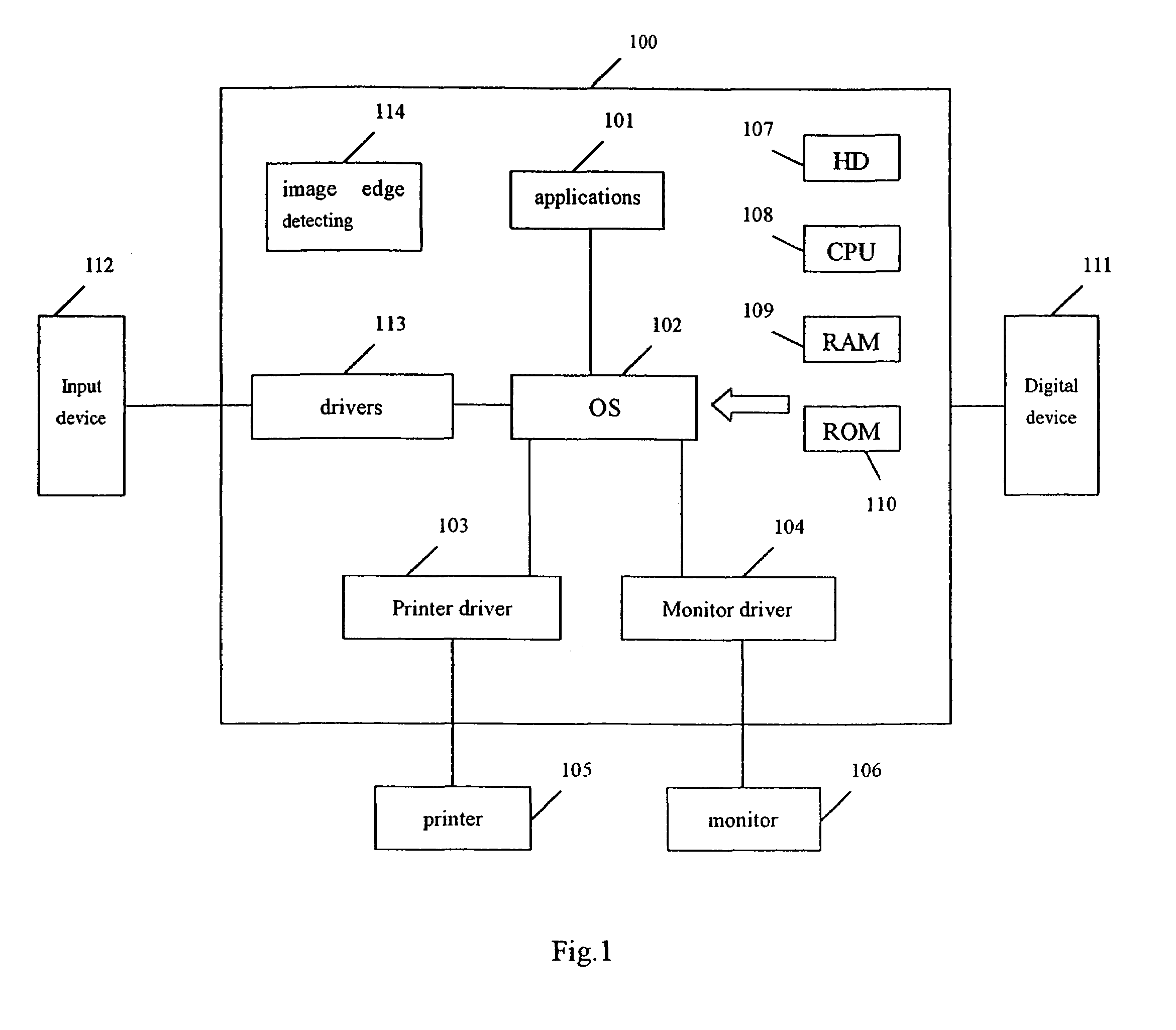
[0093]FIG. 1 shows a structural block diagram of the image edge detecting system according to the first embodiment of the present invention.

[0094]A printer 105, such as an ink jet printer and the like, and a monitor 106 are connected with a host computer 100.

[0095]The host computer 100 has an application program 101, such as a word processing program, a scaling program, an Internet browser and the like, an OS (operating system) 102, a printer driver program 103 for processing various drawing commands (image drawing command, letter drawing command, graphics drawing command) indicating output images, which are issued by the application program 101 to the OS 102, and generating printing data, and a monitor driver 104 for processing various drawing commands issued by the application program 101 and displaying data on the monitor 106.

[0096]Reference number 112 denotes an instruction inputting device, and 113 denotes its device driver, for example, a mouse is connected, ...

second embodiment

[0221]Due to needs in practical application, such as typesetting etc., an image sometime may contains one or more large title blocks, as shown in FIG. 12A; moreover, an image may further contains some inverted characters (i.e., white characters in black background). Such blocks appear as an independent peak(s) in histogram, such as shown in FIG. 12B, thus changing the distribution of the foreground and background and resulting in undesired effect on finding an appropriate edge criterion.

[0222]To solve such problems, a step for modifying the histogram is added into an embodiment as shown in FIG. 3, thereby providing a second embodiment of the present invention, as shown with the flowchart of FIG. 3A.

[0223]The image edge detecting system according to the second embodiment differs from the system according to the first embodiment (that is, the system as shown in FIG. 1) only in that the image edge detecting apparatus 114 according to the first embodiment is replaced by the image edge d...


PUM


Abstract

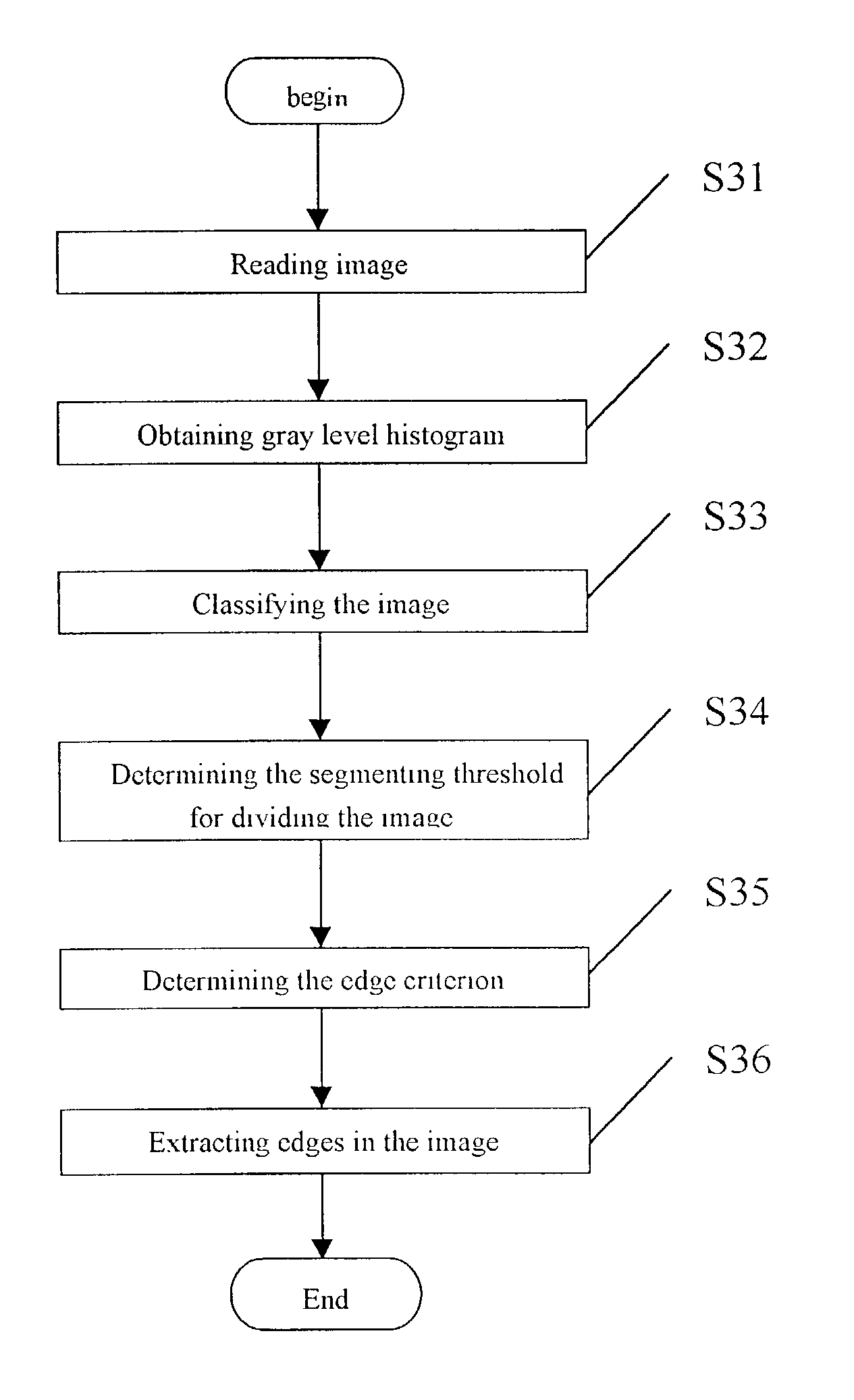
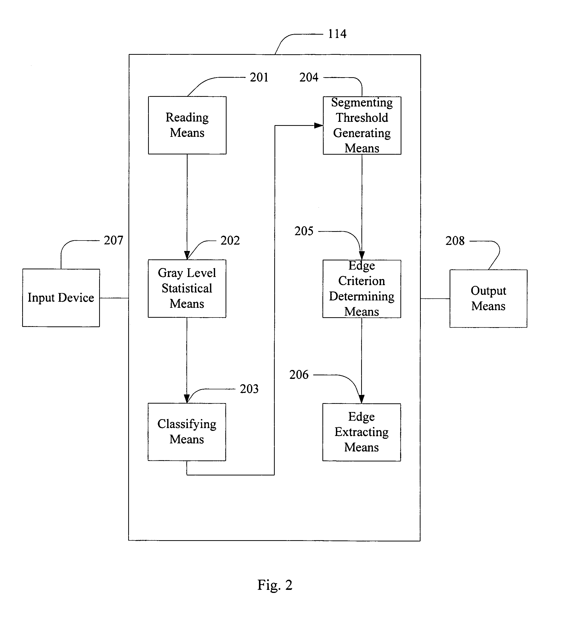
A method for detecting edges in an image is disclosed along with corresponding apparatus and system for accurately extracting edges in the image. The edge detecting apparatus comprises a reading means, an image gray-level statistical means, an image classification means, a segmenting threshold generating means, an edge criterion determining means, and an image edge extracting means. The present invention realizes a reliable and accurate method for detecting edges in an image so as to extract edges in various file images.

Description

FIELD OF THE INVENTION[0001]The present invention relates to an image processing method and apparatus as well as an image processing system, particularly relates to a method, apparatus, and system for detecting edges in an image, and storage medium.BACKGROUND OF THE INVENTION[0002]It is often desired that an input image from an input device such as scanner or digital camera can be reproduced with high quality. To produce a digital quality with high quality, appropriate image process needs to be performed on input image. With the current digital image processing technology, an image of high quality can be generated.[0003]However, problems exist in the prior art image processing technology. In general, an input image can be divided into a character portion, a photographic portion, and a dot portion. When a dot image is processed using a filtering method, due to the influence of sampling rate and pixel, the input image often blurs. On the other hand, when a file containing a dot image,...

Claims


Application Information

Patent Timeline
Patent Type & Authority Patents(United States)
IPC IPC(8): G06K9/00G06T1/00H04N1/40G06T5/00G06T7/00G06T7/60H04N1/403
CPCG06T7/0081H04N1/4092G06K9/00456G06T2207/10008G06T2207/20148G06T2207/30176G06T2207/20144G06T7/11G06T7/194G06T7/136G06V30/413G06T1/00
Inventor LI, YULINWANG, JIEZHAO, HONGSHENG
Owner CANON KK
Learn More