
Stacked capacitor

a technology of stacked capacitors and capacitors, applied in the direction of stacked capacitors, fixed capacitor details, fixed capacitors, etc., can solve the problems of cpu malfunction, large voltage drop, voltage drop, etc., and achieve rapid charging and discharging, rapid change, and large current

Active Publication Date: 2006-05-30
TDK CORPARATION
View PDF12 Cites 22 Cited by
  • Summary
  • Abstract
  • Description
  • Claims
  • Application Information

AI Technical Summary

Benefits of technology

[0012]In view of the foregoing, it is an object of the present invention to provide a stacked capacitor capable of further reducing ESL in order to supply a stable voltage to a CPU or the like.

Problems solved by technology

When current flows the wire in the CPU, voltage drop is caused by inductance of the wire.
If the load current changes abruptly, larger voltage drop is caused.
If the power source applies a low voltage to the CPU, it is impossible to ignore the voltage drop since slight changes in the voltage can lead to CPU's malfunctions.
Therefore, the ESL of the decoupling capacitor itself greatly affects voltage changes since the change in current di / dt is large.

Method used


Image

  • Stacked capacitor
  • Stacked capacitor
  • Stacked capacitor

Examples


Embodiment Construction

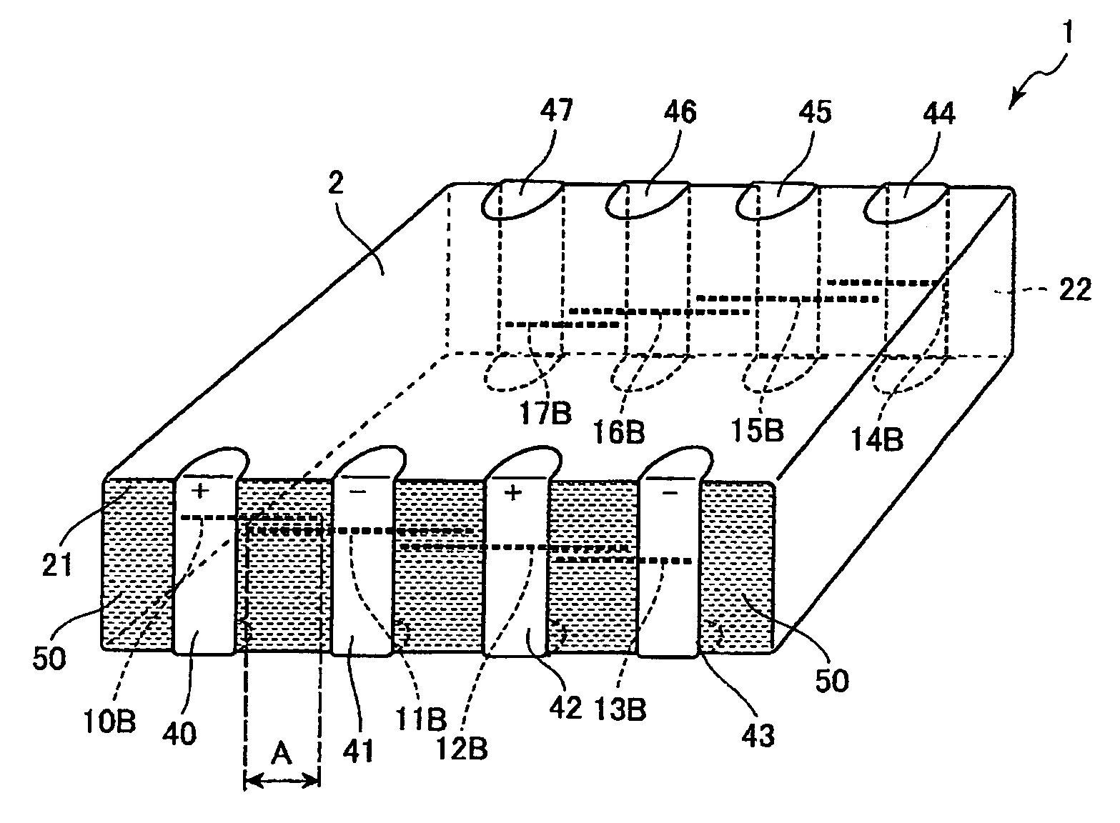
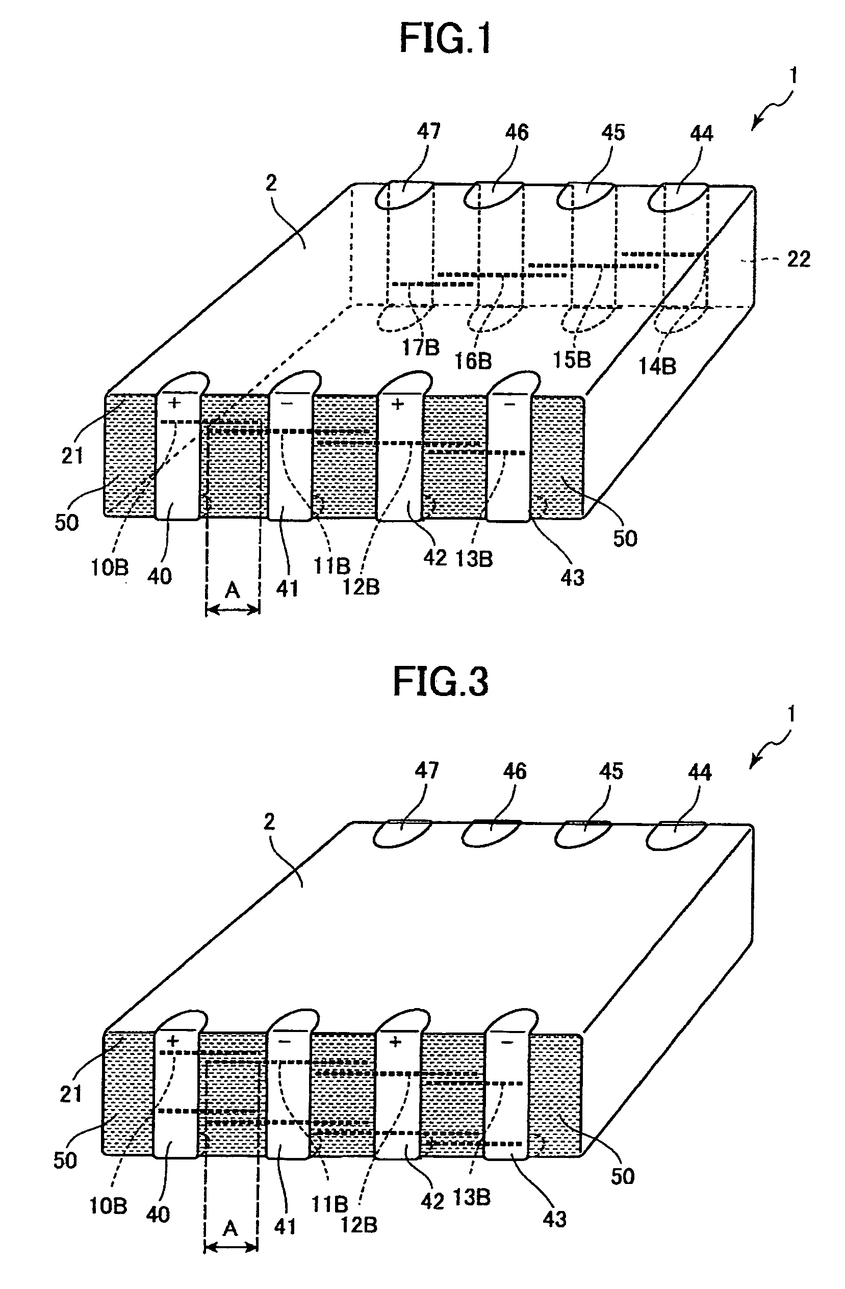
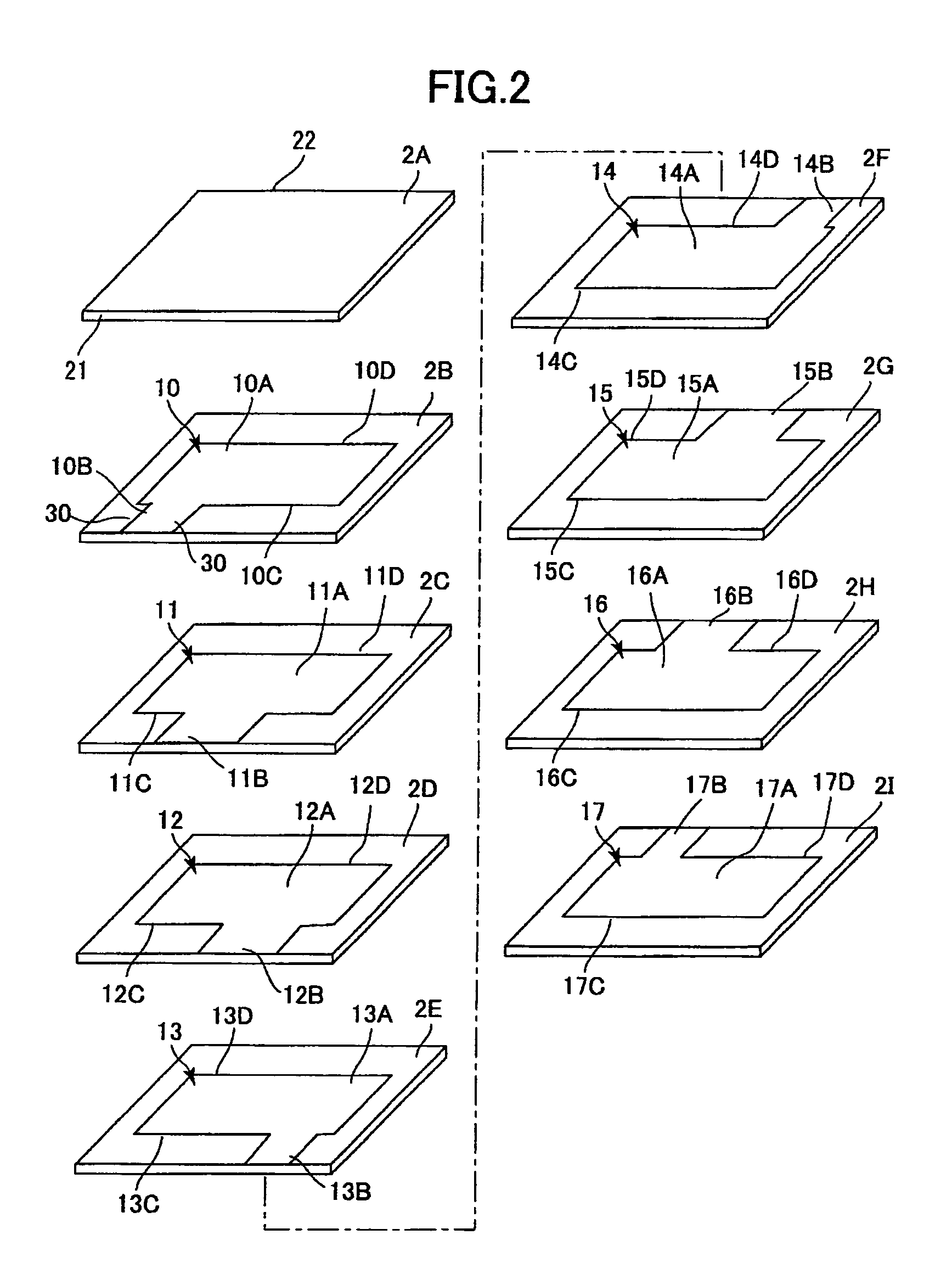
[0022]A stacked capacitor 1 according to a preferred embodiment of the present invention will be described while referring to FIGS. 1 and 2. As shown in FIGS. 1 and 2, the stacked capacitor 1 includes a dielectric member 2, first through eighth electrodes 10–17, and external electrodes 40–47. The dielectric member 2 is constructed by stacking sheet-like dielectric layers 2A–2I that are substantially rectangular in shape. The dielectric member 2 has a first side surface 21 and a second side surface 22 opposing the first side surface 21 (only indicated for the dielectric layer 2A in FIG. 2). The dielectric member 2 is manufactured by stacking ceramic green sheets serving as the dielectric layers 2A–2I and sintering the stacked structure.

[0023]The first through eighth electrodes 10–17 are formed of a base metal such as nickel or a nickel alloy, copper or a copper alloy, or a metal alloy having one of these metals as the primary component. The first through eighth electrodes 10–17 are d...


PUM

PropertyMeasurementUnit
clock frequenciesaaaaaaaaaa
frequencyaaaaaaaaaa
surface areaaaaaaaaaaa

Abstract

A stacked capacitor includes a dielectric member, a plurality of internal electrodes, and a plurality of extraction electrodes. The dielectric member is a stacked member formed of a plurality of sheet-like stacked dielectric layers and has at least one side surface. The internal electrodes fit within the surface area of the dielectric layers and are stacked alternately with the dielectric layers. Further, the internal electrodes have first edges positioned near the side surface. Each extraction electrode has an overlapping portion A overlapping another extraction electrode at the side surface in a direction orthogonal to the mounting direction.

Description

BACKGROUND OF THE INVENTION[0001]1. Field of the Invention[0002]The present invention relates to a stacked capacitor capable of reducing equivalent series inductance (ESL).[0003]2. Description of Related Art[0004]In recent years, power sources have supplied lower voltages to central processing units (CPUs) provided in digital electronic equipment in order to reduce power consumption. On the other hand, as the operating frequency of today's CPUs continue to increase, it has become necessary to supply larger load currents to the CPU.[0005]When current flows the wire in the CPU, voltage drop is caused by inductance of the wire. If the load current changes abruptly, larger voltage drop is caused. If the power source applies a low voltage to the CPU, it is impossible to ignore the voltage drop since slight changes in the voltage can lead to CPU's malfunctions. Therefore, the importance of stabilizing the voltage increases.[0006]A stacked capacitor called a decoupling capacitor is connect...

Claims


Application Information

Patent Timeline
Patent Type & Authority Patents(United States)
IPC IPC(8): H01G4/30H01G4/012H01G4/232
CPCH01G4/012H01G4/30H01G4/232H01G4/12H01G4/228H01G4/38
Inventor TOGASHI, MASAAKIFUKUNAGA, TATSUYA
Owner TDK CORPARATION
Learn More