
Electrically operated drive controller, electrically operated drive control method and its program

a technology of electric drive controller and drive motor, which is applied in the direction of electric controller, dynamo-electric converter control, instruments, etc., can solve the problems of insufficient generation of drive motor torque and ineffective performance of weak field control, and achieve the effect of effectively performing weak field control and sufficiently generating torque of electrically operated machines

Active Publication Date: 2006-05-30
AISIN AW CO LTD
View PDF8 Cites 19 Cited by
  • Summary
  • Abstract
  • Description
  • Claims
  • Application Information

AI Technical Summary

Benefits of technology

"The present invention provides an electrically operated drive controller, method, and program that can effectively perform weak field control and generate sufficient torque for an electrically operated machine. The controller includes first and second electric current command value calculation processing means, voltage command value calculation processing means, and first and second adjusting value calculation processing means. The first electric current command value is adjusted based on the first adjusting value and is limited to a predetermined value. The second electric current command value is adjusted based on the second adjusting value as the first electric current command value is limited. This allows for a more precise control of the electrically operated machine."

Problems solved by technology

However, in the conventional drive motor controller, when the d-axis electric current command value becomes excessively large in the negative direction, weak field control can not be effectively performed, and drive motor torque can not be sufficiently generated.

Method used


Image

  • Electrically operated drive controller, electrically operated drive control method and its program
  • Electrically operated drive controller, electrically operated drive control method and its program
  • Electrically operated drive controller, electrically operated drive control method and its program

Examples


Embodiment Construction

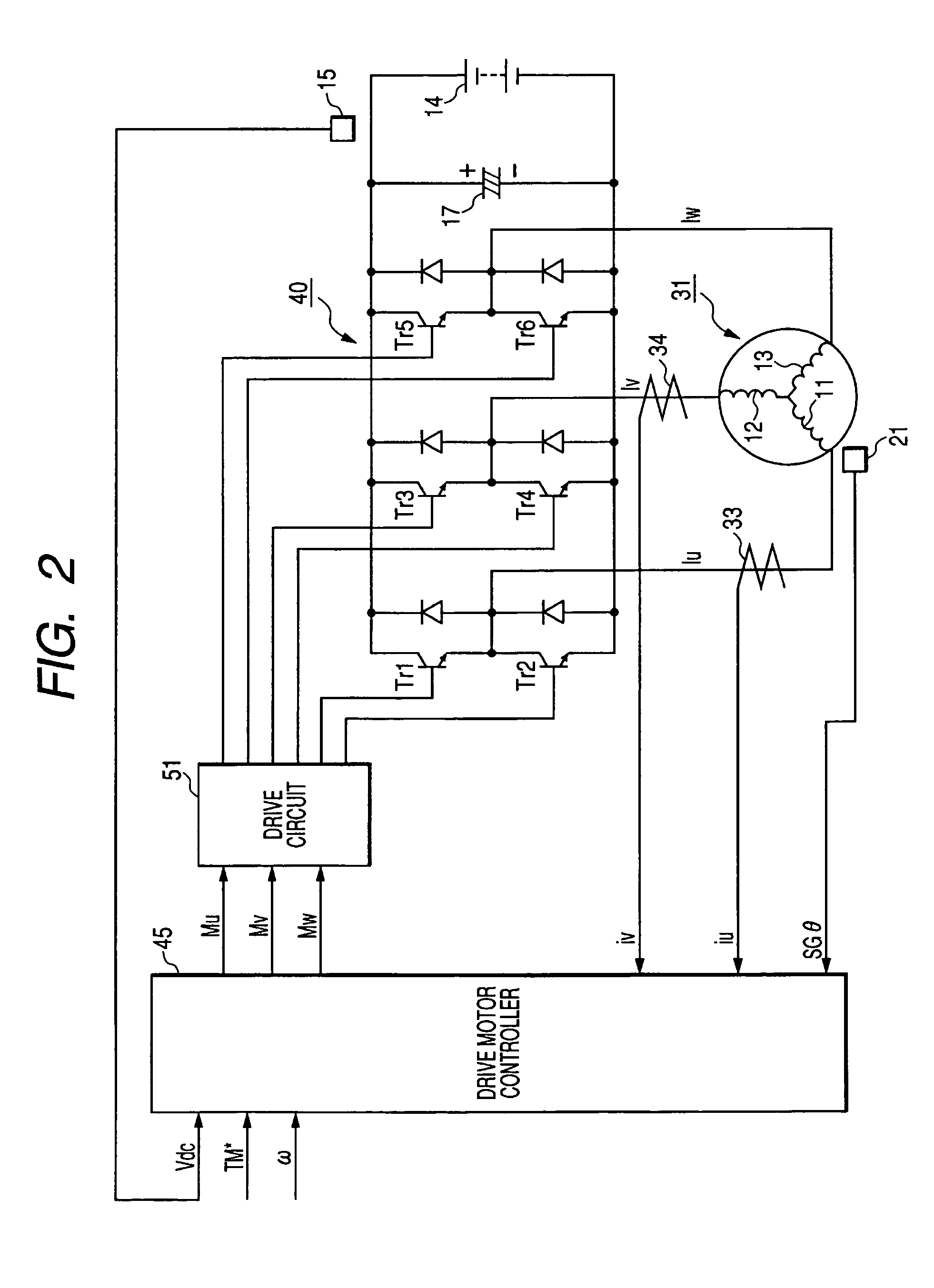
[0031]Exemplary embodiments of the present invention will next be explained in detail with reference to the drawings. An electrically operated drive unit mounted to an electric automobile as an electrically operated vehicle, and an electrically operated drive controller for operating this electrically operated drive unit will be explained.

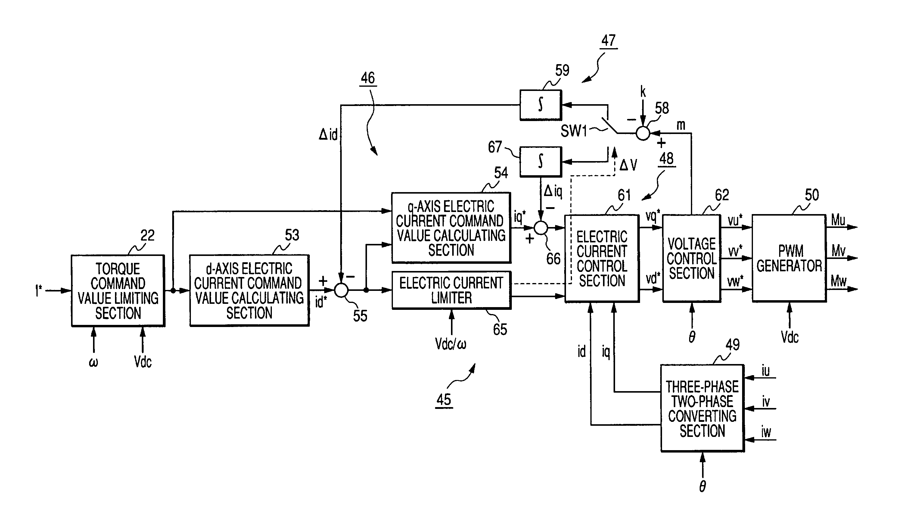
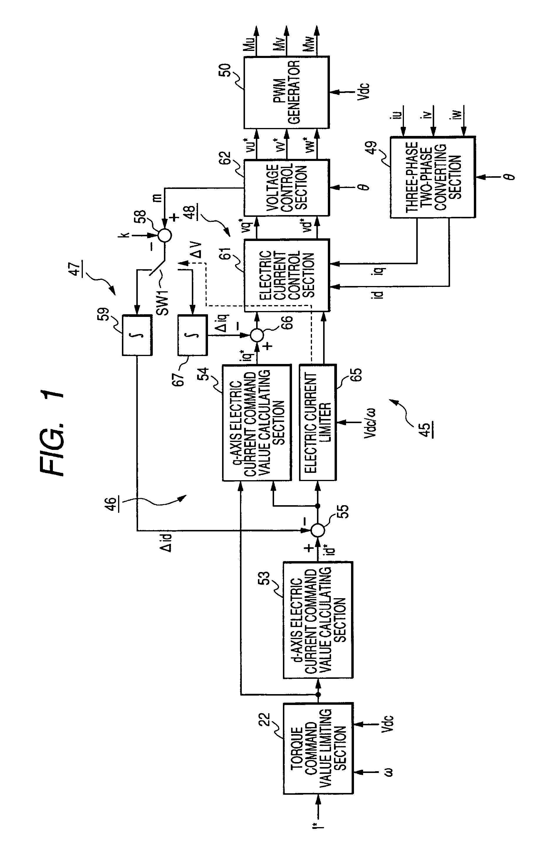
[0032]FIG. 1 is a block diagram of a drive motor controller of a first embodiment of the present invention. FIG. 2 is a conceptual view of an electrically operated drive unit of the first embodiment of the present invention. FIG. 3 is a maximum drive motor target torque map of the first embodiment of the present invention. FIG. 4 is a first electric current command value map of the first embodiment of the present invention. FIG. 5 is a second electric current command value map of the first embodiment of the present invention. FIG. 6 is an electric current limit map of the first embodiment of the present invention. In FIG. 3, angular velocity ω is m...


PUM


Abstract

An electrically operated drive controller includes first and second electric current command value calculation processors, for calculating first and second electric current command values from a target value of torque of an electrically operated machine; a voltage command value calculation processor, for calculating a voltage command value from the first and second electric current command values; and first and second adjusting value calculation processor, for calculating first and second adjusting values. The first electric current command value calculation processor includes first electric current command value adjustment processors, for adjusting the first electric current command value by the first adjusting value, and an electric current limit processor, for limiting the adjusted first electric current command value. The second electric current command value calculation processor includes a second electric current command value adjustment processor, for adjusting the second electric current command value by the second adjusting value.

Description

[0001]This application claims priority to Japanese Patent Application JP 2004-190738, filed in the Japanese Patent Office on Jun. 29, 2004, the disclosure of which is incorporated herein by reference.BACKGROUND OF THE INVENTION[0002]1. Field of the Invention[0003]The present invention relates to an electrically operated drive controller, an electrically operated drive control method and its program.[0004]2. Background Art[0005]A rotor, rotatably arranged and having a magnetic pole pair including a permanent magnet of the N-pole and the S-pole; a stator, arranged radially outward from this rotor and having stator coils of U-phase, V-phase and W-phase, etc., are arranged in a drive motor or an electric generator provided as an electrically operated machine.[0006]An electrically operated drive unit is provided to drive the drive motor or the electric generator and to generate drive motor torque (torque of the drive motor), or electric generator torque (torque of the electric generator)...

Claims


Application Information

Patent Timeline
Patent Type & Authority Patents(United States)
IPC IPC(8): G05B11/36G05B11/00H02P27/04H02P7/00H02P21/00H02P21/06H02P21/13H02P21/22
CPCB60L11/1803B60L15/025H02P21/0035H02P21/06Y02T10/7258Y02T10/643Y02T10/7005B60L50/51H02P21/22Y02T10/64Y02T10/70Y02T10/72
Inventor CHEN, ZHIQIANFUJIWARA, ISAO
Owner AISIN AW CO LTD
Learn More