
Thin-film solar cell fabricated on a flexible metallic substrate

a technology of flexible metallic substrate and solar cell, which is applied in the direction of solid-state devices, pv power plants, semiconductor devices, etc., can solve the problems of increasing the cost of positioning the satellite into orbit and operating costs, reducing the payload of the satellite, and increasing the launch weigh

Inactive Publication Date: 2006-05-30
ALLIANCE FOR SUSTAINABLE ENERGY
View PDF32 Cites 156 Cited by
  • Summary
  • Abstract
  • Description
  • Claims
  • Application Information

AI Technical Summary

Problems solved by technology

Accordingly, the weight of an array or battery of such prior art solar cells is a determining factor in the size of the battery system to be launched into space due to payload weight constraints.
Heavy solar cells increase the cost of positioning the satellite into orbit and the operating costs by reducing the payload of the satellite and increasing the launch weight.

Method used


Image

  • Thin-film solar cell fabricated on a flexible metallic substrate
  • Thin-film solar cell fabricated on a flexible metallic substrate
  • Thin-film solar cell fabricated on a flexible metallic substrate

Examples


Embodiment Construction

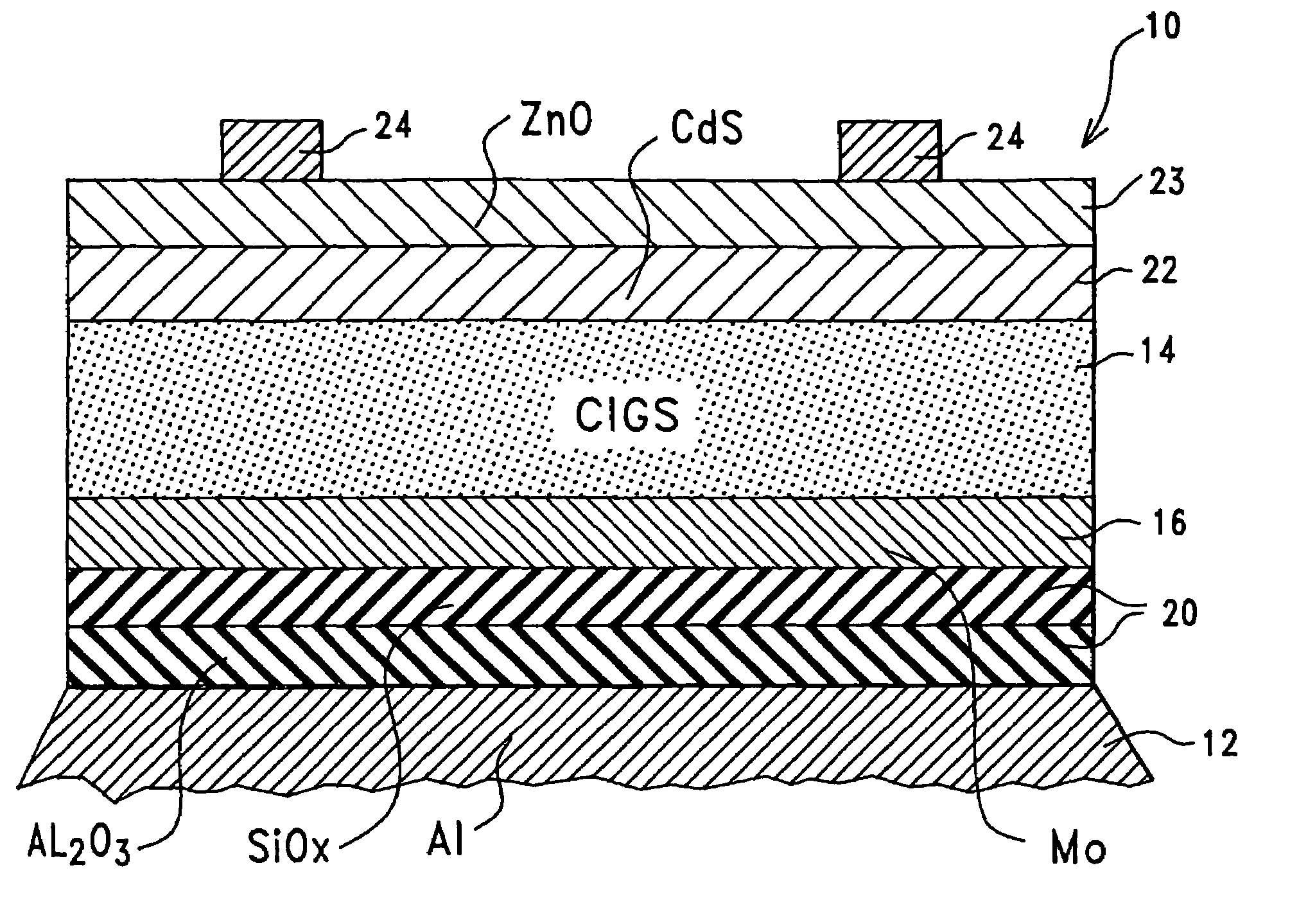
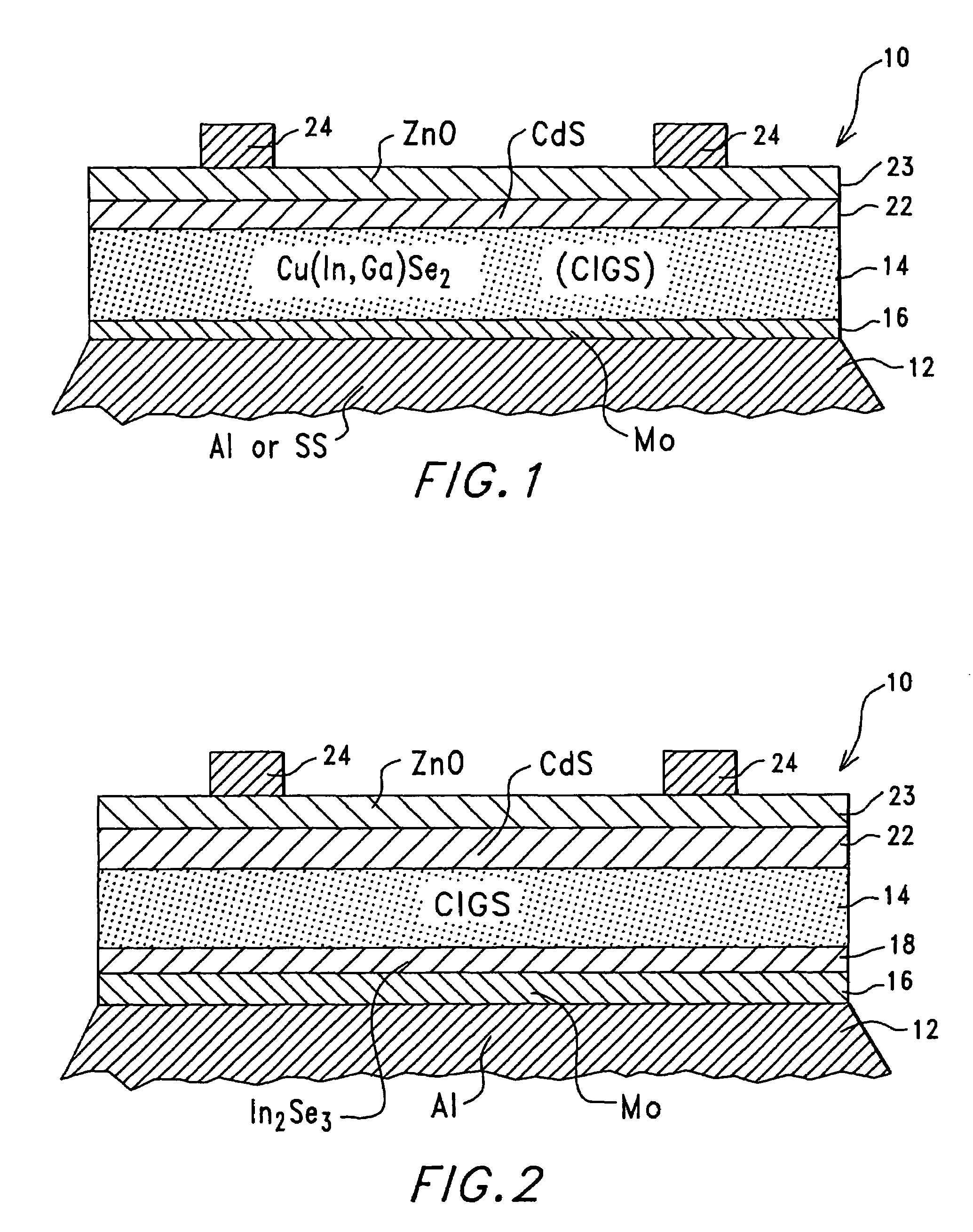
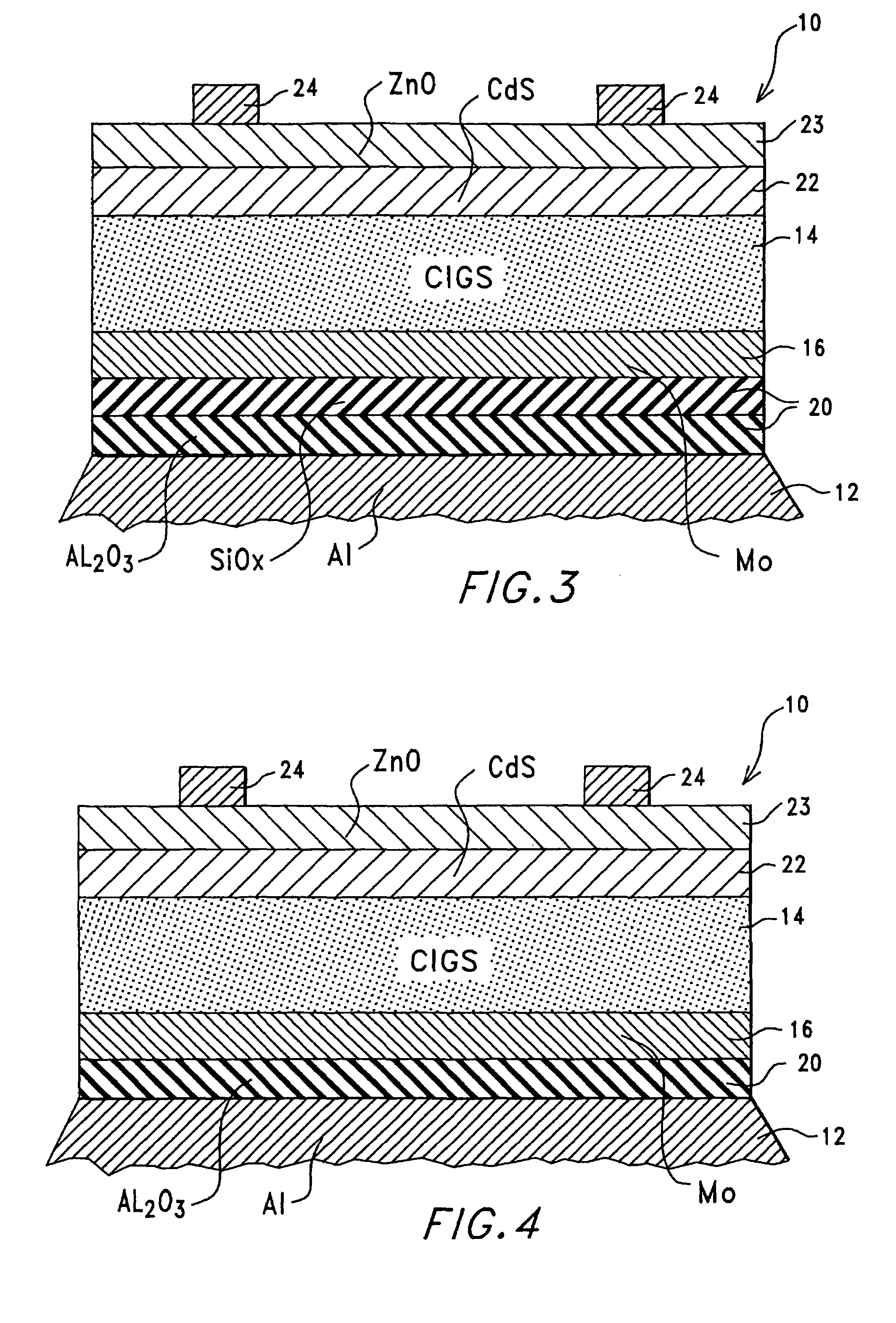
[0016]As illustrated in FIG. 1, the present invention is a thin-film solar cell, indicated generally at 10. The thin-film solar 10 cell has a flexible metallic substrate 12 preferably constructed from an Aluminum (Al) material or a stainless steel material and a semiconductor absorber layer 14 deposited on the flexible metallic substrate 12. The surface of the flexible metallic substrate 12 can be polished (to benefit the film structure of the absorber layer 14 and morphology) or it may be textured (to increase the path length of the reflected light). A chromium adhesion layer, although not always required, can be added to increase adhesion, i.e., a chromium adhesion layer between approximately 100 Å and 400 Å. Furthermore, the flexible metallic substrate 12 can be thin and flexible, i.e., approximately 25 μm to approximately 100 μm, in order that the thin-film solar cell 10 is lightweight, or the flexible metallic substrate 12 can be thick and rigid to improve handling of the thin-...


PUM


Abstract

A thin-film solar cell (10) is provided. The thin-film solar cell (10) comprises a flexible metallic substrate (12) having a first surface and a second surface. A back metal contact layer (16) is deposited on the first surface of the flexible metallic substrate (12). A semiconductor absorber layer (14) is deposited on the back metal contact. A photoactive film deposited on the semiconductor absorber layer (14) forms a heterojunction structure and a grid contact (24) deposited on the heterjunction structure. The flexible metal substrate (12) can be constructed of either aluminium or stainless steel. Furthermore, a method of constructing a solar cell is provided. The method comprises providing an aluminum substrate (12), depositing a semiconductor absorber layer (14) on the aluminum substrate (12), and insulating the aluminum substrate (12) from the semiconductor absorber layer (14) to inhibit reaction between the aluminum substrate (12) and the semiconductor absorber layer (14).

Description

CONTRACTUAL ORIGIN OF THE INVENTION[0001]The United States Government has rights in this invention under Contract No. DE-AC36-99GO10337 between the United States Department of Energy and the National Renewable Energy Laboratory, a division of the Midwest Research Institute.TECHNICAL FIELD[0002]This invention relates generally to a thin-film solar cell and, more particularly, to a thin-film solar cell fabricated on a flexible metallic aluminum or stainless steel substrate with appropriate means for inhibiting reaction between the aluminum substrate and the semiconductor absorber.BACKGROUND ART[0003]Photovoltaic devices, i.e., solar cells, are capable of converting solar radiation into usable electrical energy. The energy conversion occurs as the result of what is known as the photovoltaic effect. Solar radiation impinging on a solar cell and absorbed by an active region of semiconductor material generates electricity.[0004]In recent years, technologies relating to thin-film solar cel...

Claims


Application Information

Patent Timeline
Patent Type & Authority Patents(United States)
IPC IPC(8): H01L31/00H01L21/00H01L31/032H01L31/0392
CPCH01L31/0322H01L31/03928Y02E10/541
Inventor TUTTLE, JOHN R.NOUFI, ROMMELHASOON, FALAH S.
Owner ALLIANCE FOR SUSTAINABLE ENERGY
Learn More