
Photoelectrochemical device and electrode

a photoelectrochemical and electrode technology, applied in the field of photoelectrochemical devices and electrodes, can solve the problems of less robust inner metal oxide layer with respect to aggressive attack by electrolytic solutions, and achieve the effect of reducing the risk of electrolytic reaction

Active Publication Date: 2006-05-30
GM GLOBAL TECH OPERATIONS LLC
View PDF40 Cites 50 Cited by
  • Summary
  • Abstract
  • Description
  • Claims
  • Application Information

AI Technical Summary

Benefits of technology

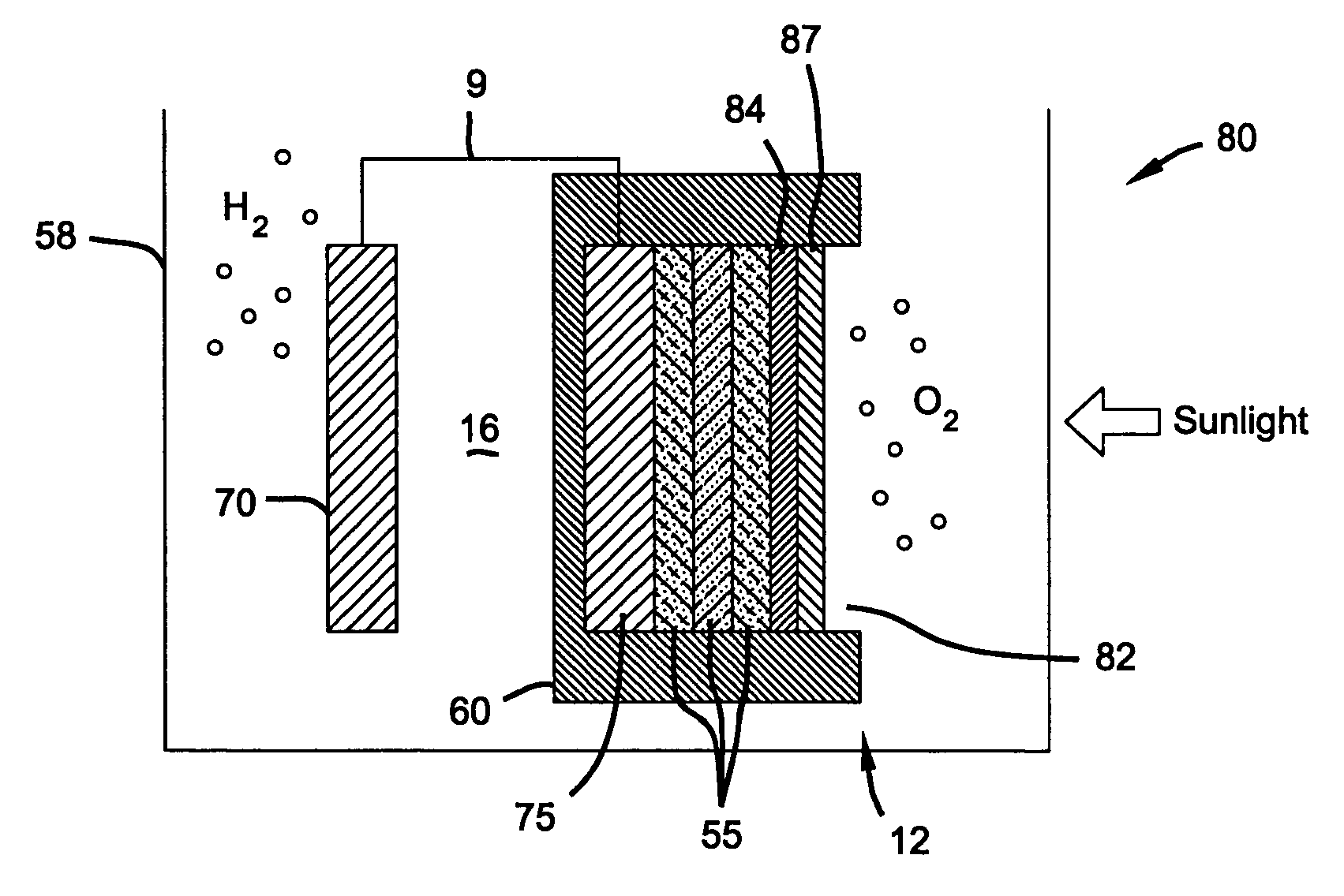
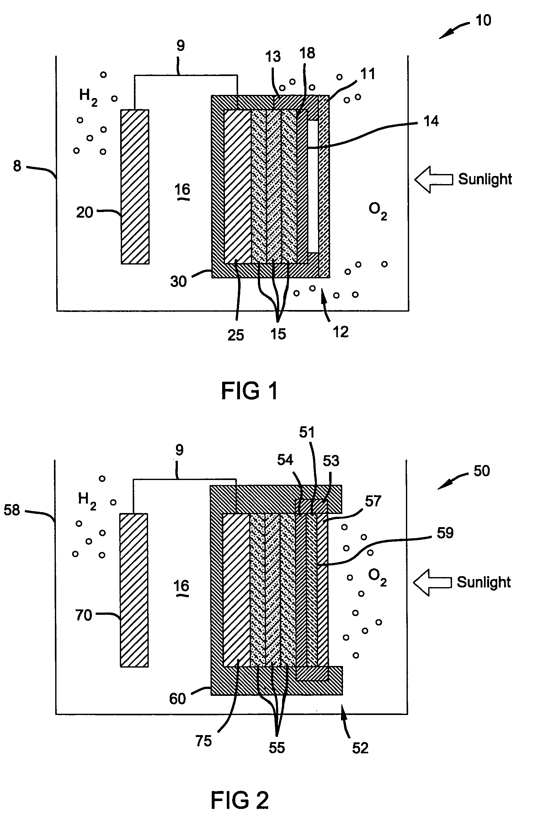
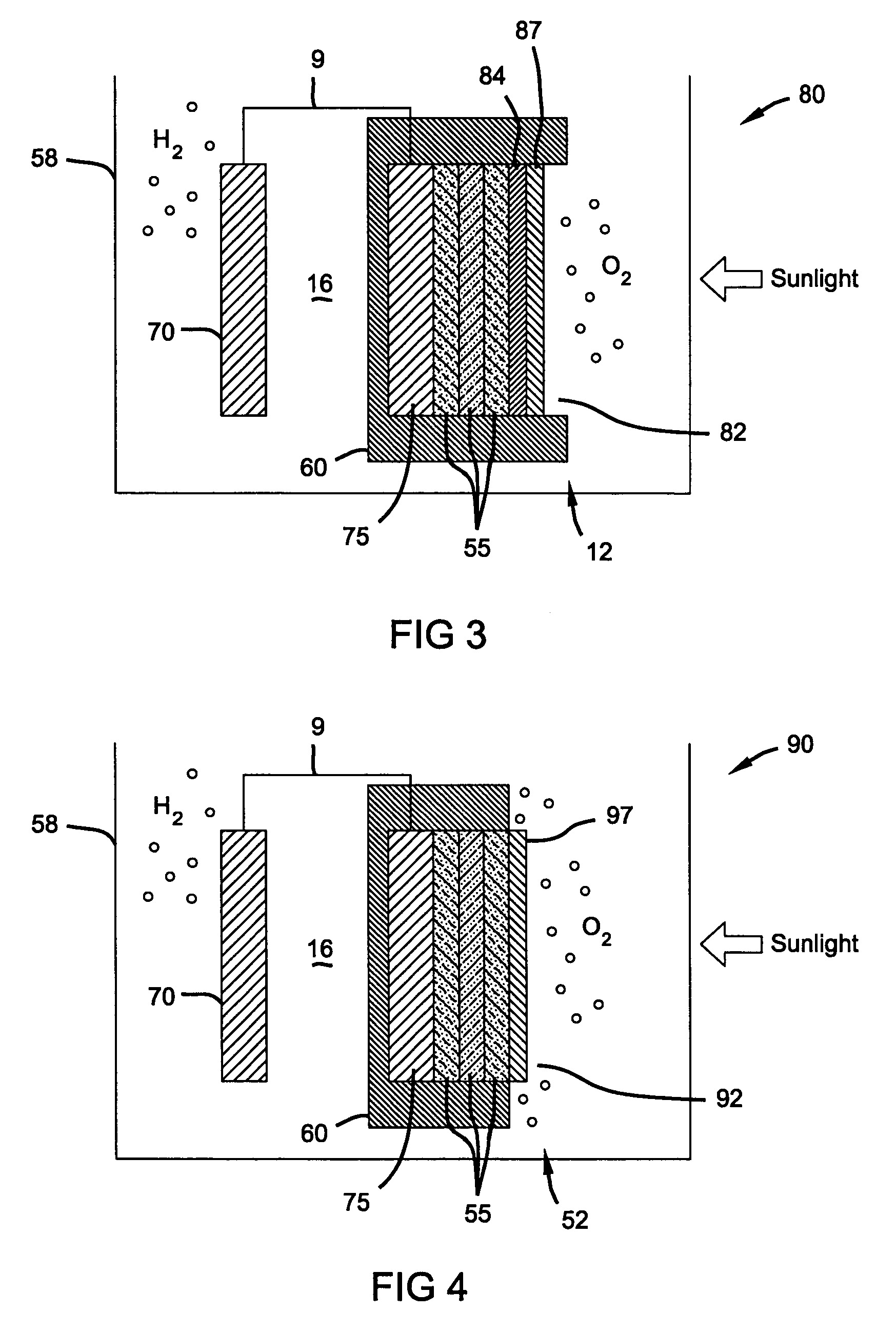
[0006]In another embodiment, the semiconductor material of the photoelectrode is overlaid with a transparent, anti-reflective, electrically conductive metal oxide layer and such layer is protected by being overlaid with a non-conductive, transparent material, preferably glass, polymer, or plastic which is impervious to the electrolyte solution. The amorphous semiconductor layer has a peripheral surface and an electrically conductive material that in one embodiment is in contact with at least a portion of the peripheral surface of the semiconductor layer and is in contact with the TCO layer. The electrically conductive material preferably consists of a metal, metal polymer composite, or conductive sealant. By this arrangement, an electrically conductive path is provided from the semiconductor layer to the TCO layer and then to the electrically conductive material that is exposed to the electrolyte solution. The transparent insulative layer protects the TCO layer from contact with the aggressive electrolyte solution.

Problems solved by technology

Electrolyte solutions aggressively attack many kinds of surfaces including some metals and metal oxides by corrosion and dissolution.
This inner metal oxide layer may be less robust with respect to aggressive attack by the electrolytic solution than the doped tin oxide layer.

Method used


Image

  • Photoelectrochemical device and electrode
  • Photoelectrochemical device and electrode
  • Photoelectrochemical device and electrode

Examples


Embodiment Construction

[0015]The following description of the preferred embodiment(s) is merely exemplary in nature and is in no way intended to limit the invention, its application, or uses.

[0016]In one aspect of the present invention, there is provided a photoelectrochemical (PEC) device for electrolysis of water to produce hydrogen. The PEC device comprises a container housing a photoelectrochemical (PEC) electrode (photoelectrode), a counter electrode and an electrolyte solution. In a preferred aspect of the PEC device the TCO-coated photoelectrode is the anode and produces oxygen, while the counter electrode is the cathode and produces hydrogen. The photoelectrode and the counter electrode are spaced apart from one another in the container, and each electrode is in contact with the electrolyte solution. Preferably, the counter electrode comprises a metal such as Pt or Ni that is stable under the reducing conditions at the cathode and has a low overvoltage for hydrogen production. The electrolyte solu...


PUM

PropertyMeasurementUnit
voltageaaaaaaaaaa
irradianceaaaaaaaaaa
current densityaaaaaaaaaa

Abstract

In one aspect, the invention provides a photoelectrochemical (PEC) electrode or photoelectrode for use in splitting water by electrolysis. The photoelectrode has an electrically conductive surface in contact with an electrolyte solution. This surface is a doped tin oxide layer, which is in electrical contact with the semiconductor solar cell material of the PEC photoelectrode. In a variation of the present invention, another layer of metal oxide having transparent, anti-reflective, and conductive properties is disposed between the doped tin oxide layer and the semiconductor material.

Description

FIELD OF THE INVENTION[0001]This invention relates to photoelectrochemical (PEC) devices for the solar photoelectrolysis of water to produce hydrogen.BACKGROUND OF THE INVENTION[0002]Currently the major process by which hydrogen is produced is by the steam reforming of methane. Another means of making hydrogen is by the electrolysis of water. The electricity required for electrolysis is mainly derived from the electric power grid, and the predominant source of grid electricity, combustion of fossil fuels, generates emissions, such as nitrogen oxides and particulate matter, as well as carbon dioxide. One way to eliminate such emissions is to use solar generated electricity to electrolyze water to make hydrogen. Presently, efforts are directed toward improving the efficiency, durability, and cost of the hydrogen production processes.[0003]However, systems consisting of solar cells to make electricity together with electrolyzers to dissociate water into hydrogen and oxygen are costly c...

Claims


Application Information

Patent Timeline
Patent Type & Authority Patents(United States)
IPC IPC(8): C25B11/00C25B1/00H01G9/20
CPCC25B1/003H01G9/2027H01G9/2045Y02E60/368Y02E10/542Y02E60/36Y02P20/133Y02P70/50C25B1/55C25B11/04C25B1/04H01L31/04C23C14/08
Inventor GIBSON, THOMAS LKELLY, NELSON A
Owner GM GLOBAL TECH OPERATIONS LLC
Learn More