
Cable winding device with direct cable to electrical component connection

a winding device and direct connection technology, applied in the direction of coupling device connection, arrangement using take-up reel/drum, non-rotary current collector, etc., can solve the problems of increasing the cost of the cable winding device, brush contacts may have a shorter cycle life, less reliability, etc., to facilitate the constraining of knots and relieve strain

Inactive Publication Date: 2006-05-30
PLANTRONICS
View PDF5 Cites 40 Cited by
  • Summary
  • Abstract
  • Description
  • Claims
  • Application Information

AI Technical Summary

Benefits of technology

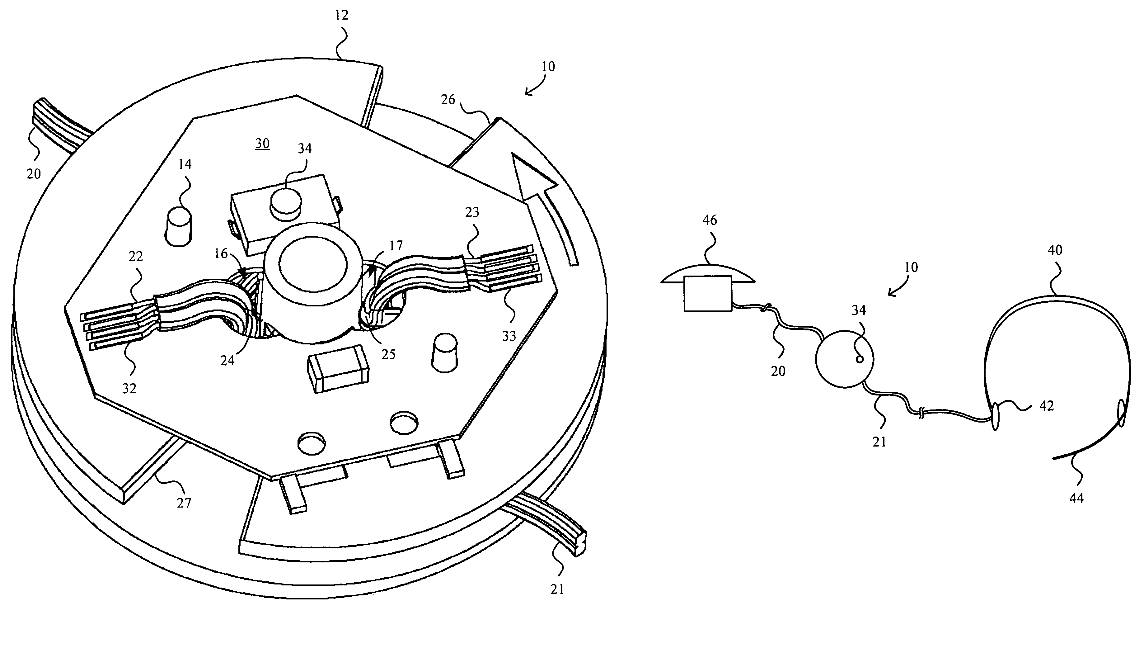
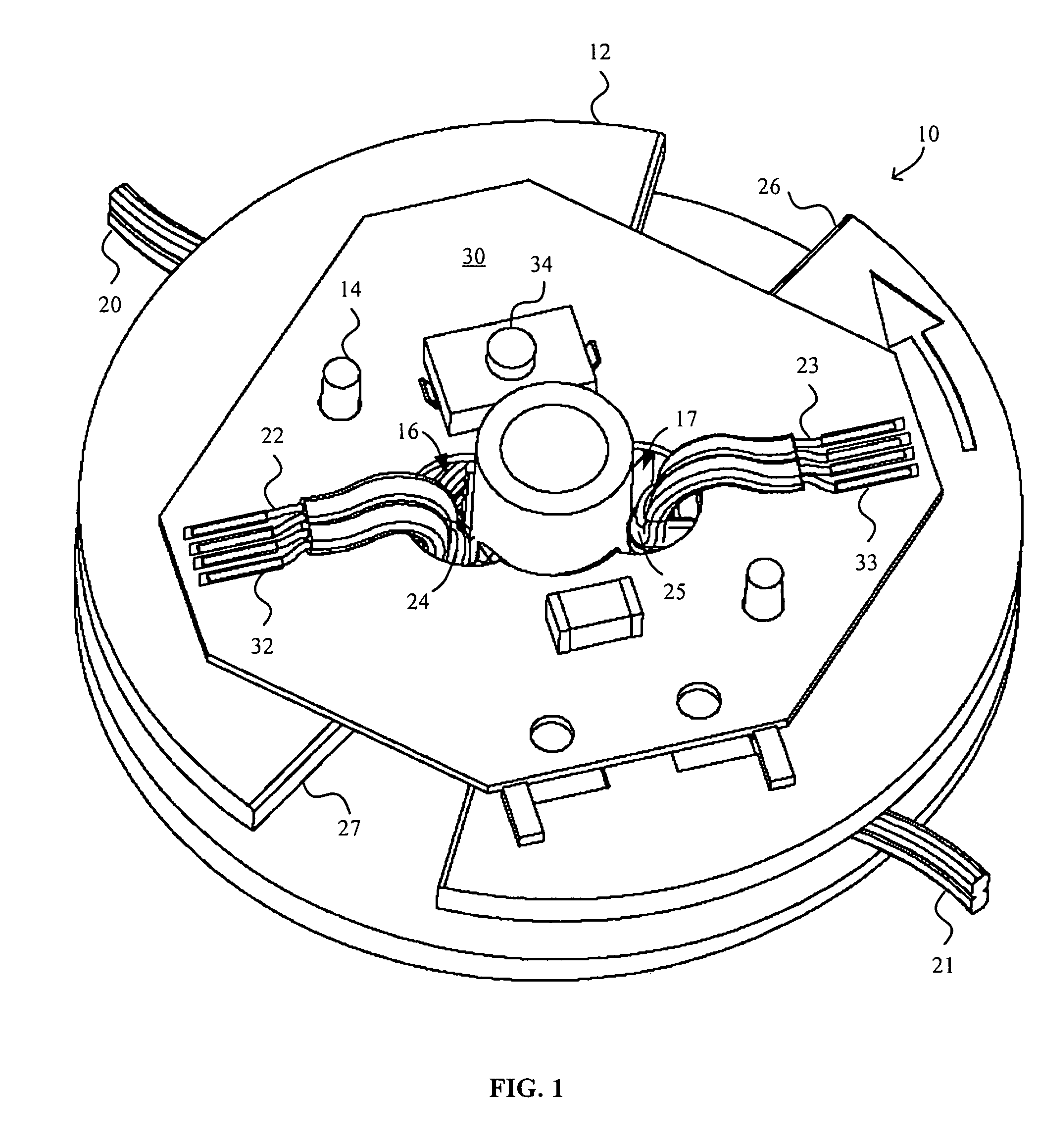
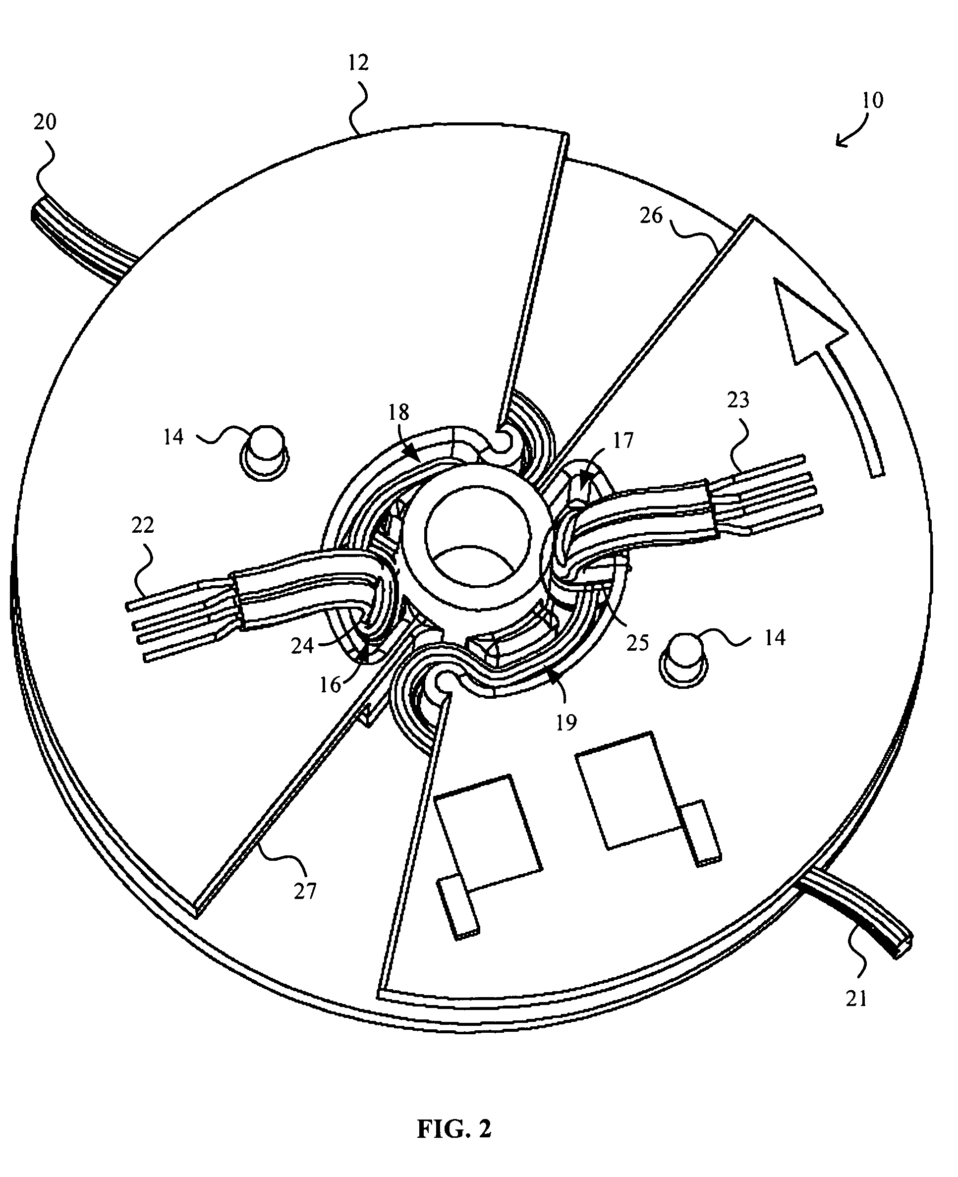
[0012]The spool may be a single mid-cable take-up spool or a pair of mid-cable take-up spools. The circuit component may be coupled to the spool via, for example, connection pins provided on the spool that cooperate with corresponding openings defined in the circuit component. The spool can provide a strain relieving cable housing configured to relieve strain exerted on the cable segments from forces applied to the cable segments such as at the headset and / or jack end of cable segments and thus protect the electronic connections from such strains. For example, the strain relieving cable housing may include a knot compartment for constraining a knot formed in each cable segment adjacent the electronic connection. The strain relieving cable housing may additionally or alternatively include a cable path or labyrinth. The cable path may correspond to each knot to facilitate in constraining the knot within the corresponding knot compartment.

Problems solved by technology

However, such constant contact between the brush contacts and the circular contact rings results in the brush contacts rubbing against the corresponding circular contact ring each time the cable is wound or unwound.
Thus the brush contacts may have a shorter cycle life and may be less reliable than a direct connection to a circuit component or PCB.
Brush contacts are also relatively expensive.
A large number of contact rings and brush contacts not only increases the cost of the cable winding device but may also necessitate a larger PCBA and thus a larger cable winding device in order to provide the area needed for the desired number of contact rings.

Method used


Image

  • Cable winding device with direct cable to electrical component connection
  • Cable winding device with direct cable to electrical component connection
  • Cable winding device with direct cable to electrical component connection

Examples


Embodiment Construction

[0019]Cable winding devices and mechanisms for providing direct cable to electrical component connections without brush contacts are disclosed. The examples of cable winding devices described herein may be utilized in audio headset applications such as telephone headsets, audio listening headsets, and other personal listening devices. However, it is to be understood that the cable winding devices and mechanisms described herein may be similarly applied to various other applications such as power cords for household appliances, cables associated with peripherals (e.g., keyboard, mouse, speaker, etc.) for electronic devices such as computer, personal digital assistant (PDA), cellular telephones, sound recording device, and the like. The following description is presented to enable any person skilled in the art to make and use the invention. Descriptions of specific embodiments and applications are provided only as examples and various modifications will be readily apparent to those sk...


PUM


Abstract

Cable winding devices and mechanisms for providing direct cable to electrical component connections without brush contacts are disclosed. Electronic controls may be provided directly on the cable winding device. The cable winding device generally includes two cable segments physically disconnected from each other, a spool configured for winding the cable segments thereon, and a circuit component such as a printed circuit board assembly that rotates with the spool. The circuit component may include electrical contacts to electronically connect corresponding pairs of wires of the cable segments and a user-adjustable or user-actuatable electronic control in communication with the electrical contacts. The circuit component may provide a pair of electrical contacts for each corresponding pair of wires in the cable segments and the electronic control is in communication with at least one pair of the electrical contacts. The cable segments form a continuous electrical path through a circuit component with electronic controls.

Description

BACKGROUND OF THE INVENTION[0001]1. Field of the Invention[0002]The present invention relates generally to cord winding devices. More specifically, cable winding devices and mechanisms for providing direct cable to electrical component connections without brush contacts are disclosed.[0003]2. Description of Related Art[0004]Cable or cord winding devices employing various cable winding mechanisms have been proposed and commercialized for winding various cables such as telephone cables, power cords, and the like. Cable winding devices are often provided for convenience, safety, ease of use, and / or to prevent entanglement of the cable itself and / or with other cables or objects. Cables are typically wound onto one or more take-up reels of the cable winding device.[0005]One example of a cable winding mechanism often used for telephone cables employs a pair of mid-cable take-up reels or spools positioned near the midpoint of the cable from which the take-up reels wind up the opposite segm...

Claims


Application Information

Patent Timeline
IPC IPC(8): H01R39/00
CPCH02G11/02H04M1/15
Inventor MEYBERG, JACOB T.SANDERSON, EDWARD O.BRINT, GARY T.GRATTAN, ALAN W.BRADFORD, ERIC R.
Owner PLANTRONICS
Learn More