
Thermoplastic container whereof the base comprises a cross-shaped impression

a technology of thermoplastic containers and cross-shaped impressions, which is applied in the direction of containers, container/bottle construction, rigid containers, etc., can solve the problems of inability to withstand the increased stress without deformation of the material in the bottom of the container, and the inability of the container to withstand the increased stress without deformation, etc., to achieve the effect of greater freedom in the design of the container and better stability

Inactive Publication Date: 2006-05-30
SIDEL PARTICIPATIONS SAS
View PDF10 Cites 106 Cited by
  • Summary
  • Abstract
  • Description
  • Claims
  • Application Information

AI Technical Summary

Benefits of technology

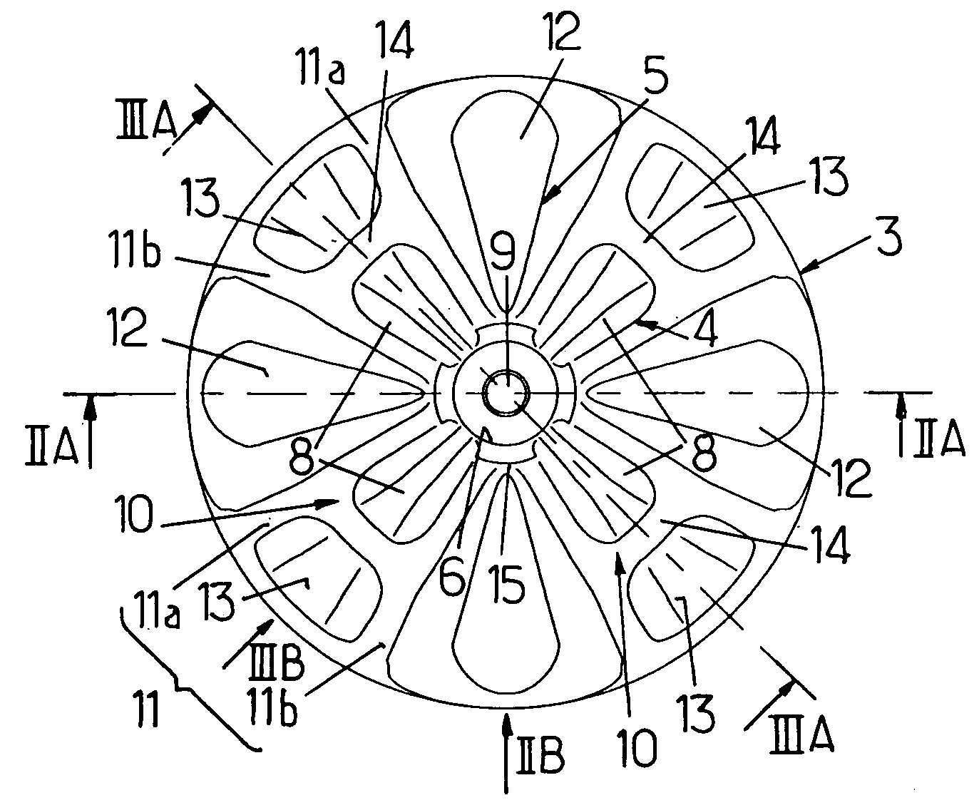
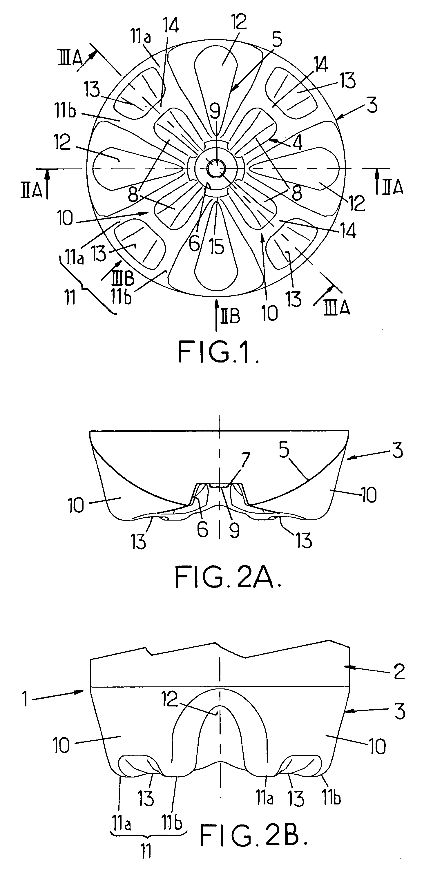
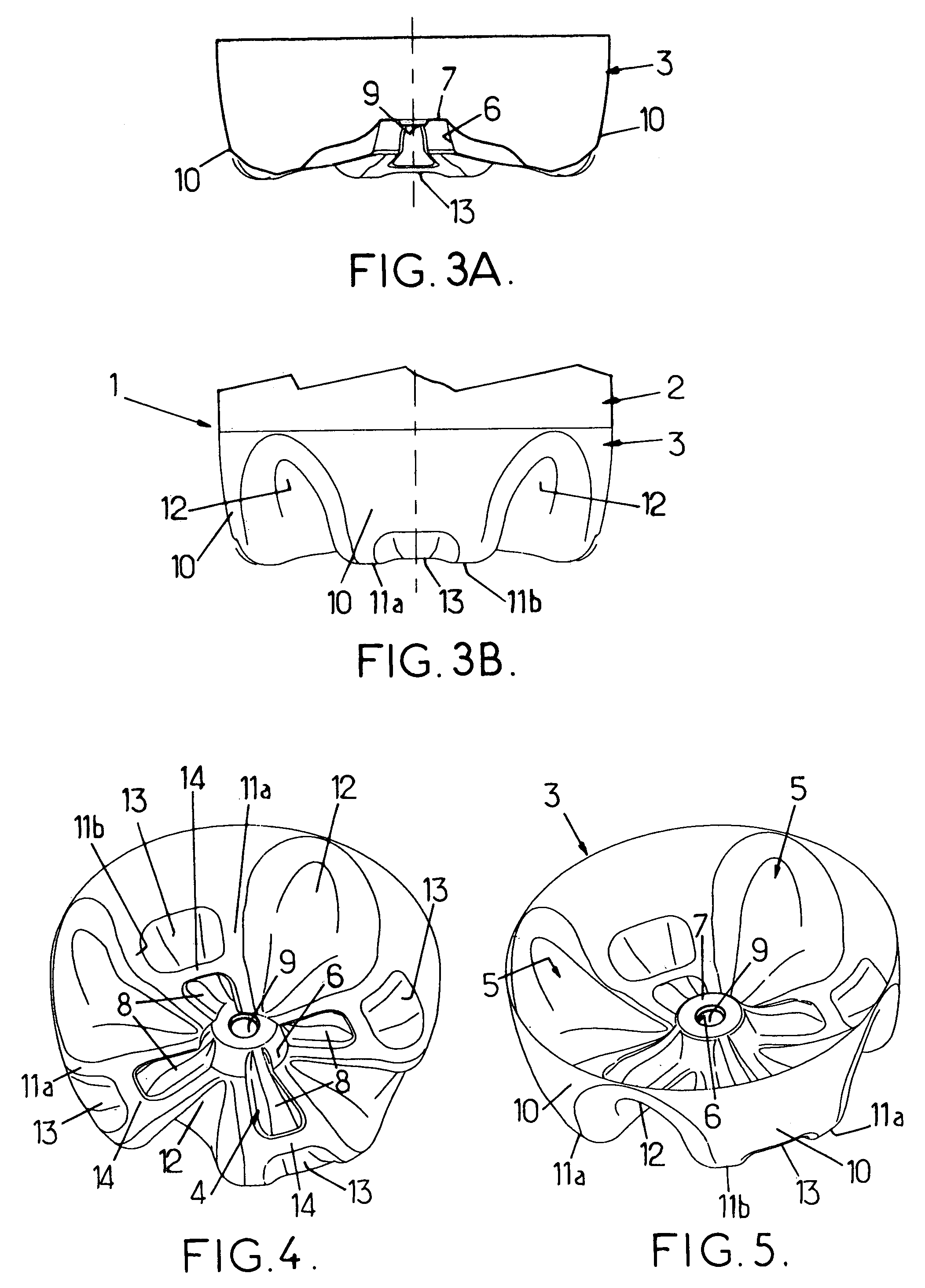
[0009]The container according to the invention combines the following positive and advantageous effects:[0010]on the one hand, of a petaloid bottom which without deformation withstands the increase in volume of the hot liquid, and[0011]on the other hand, of a bottom with a multi-branch star-shaped impression which can, without modifying the flatness of the feet of the petaloid part, deform and, by deforming inward, match the reduction in volume of the pasteurized liquid as it cools, this ability to undergo controlled deformation of the central part of the bottom (roughly in the region of the amorphous material) leading to a reduction in the deformation simultaneously experienced by the wall of the body of the container, which wall for this purpose is made in the form of juxtaposed panels; the consequence of this is that said panels provided on the wall of the body can be made with a smaller area, leaving greater freedom in the design of the container as a whole.
[0010]on the one hand, of a petaloid bottom which without deformation withstands the increase in volume of the hot liquid, and
[0011]on the other hand, of a bottom with a multi-branch star-shaped impression which can, without modifying the flatness of the feet of the petaloid part, deform and, by deforming inward, match the reduction in volume of the pasteurized liquid as it cools, this ability to undergo controlled deformation of the central part of the bottom (roughly in the region of the amorphous material) leading to a reduction in the deformation simultaneously experienced by the wall of the body of the container, which wall for this purpose is made in the form of juxtaposed panels; the consequence of this is that said panels provided on the wall of the body can be made with a smaller area, leaving greater freedom in the design of the container as a whole.
[0012]The advantages set out hereinafter still hold when the containers are filled with a still (ungasified) pasteurized liquid.
[0013]These advantages also hold, a fortiori, in the case of containers filled with a pasteurized liquid containing a dissolved gas under pressure (for example beer), these containers additionally being subjected to the raised pressure of the gases heated during pasteurization.
[0014]It will also be understood that, being able without damage to undergo the effects of pasteurization, the containers according to the invention are, a fortiori, capable without damage of undergoing hot filling (filling with a hot liquid at a temperature at most equal to about 94° C.).

Problems solved by technology

However, such containers cannot withstand a process of pasteurizing the liquid they contain (for example heat treatment at a temperature of the order of 70° C. for a time of the order of 20 minutes).
During pasteurization, the liquid sees its volume increase appreciably under the action of the temperature, and the hot material in the bottom of the container is not capable of withstanding the increased stress without deforming.
The same problem is posed a fortiori, to a greater extent, when the liquid to be pasteurized, which is contained in the container, contains dissolved gas under pressure (carbonated liquid)—the case of beer for example.
The aforesaid containers are unable to withstand such stresses without significant deformation of the bottom.

Method used


Image

  • Thermoplastic container whereof the base comprises a cross-shaped impression
  • Thermoplastic container whereof the base comprises a cross-shaped impression
  • Thermoplastic container whereof the base comprises a cross-shaped impression

Examples


Embodiment Construction

[0028]The description which follows relates more specifically, because it would seem that this is a preferred application of the arrangements of the invention, to a design of bottom for a bottle intended to contain a liquid, it being understood that this arrangement may just as easily relate to a container of another type, such as a flask or can, etc.

[0029]The invention is concerned with a container made of thermoplastic, for example of PET, obtained by blow-molding or stretch-blow-molding of a preform already obtained by molding.

[0030]The bottle, denoted in its entirety by the reference 1 in FIGS. 2B and 3B (in which only the lower part of the bottle can be seen) comprises a side wall 2 and a bottom 3 connected to this side wall.

[0031]The bottom 3 comprises, in its central region, an impression 4 in the shape of a multi-branch cross impressed into the outer face of the bottom wall 5. The cross-shaped impression 4 has a roughly circular central cup 6 (which results in a roughly roun...


PUM


Abstract

A thermoplastic container obtained by blow-molding of a preform, with a base including in its central part a multiple-branch cross-shaped impression provided with a central recess from which radial branches radiate; the base is of the petal-shaped type with at least three legs formed by protuberances located near the periphery; there are as many legs as branches mutually aligned radially; each leg includes a notch for absorbing stresses radially separated from the end of the respective branch.

Description

FIELD OF THE INVENTION[0001]The present invention relates to improvements made to thermoplastic containers, especially bottles, obtained by blow-molding or stretch-blow-molding of a preform, these containers comprising a side wall and a bottom connected to this side wall, said bottom comprising, in its central region, an impression in the shape of a multi-branch cross impressed into the outer face of the bottom wall, this cross-shaped impression having a roughly circular central hollow around which uniformly-spaced radially-extending branches radiate.DESCRIPTION OF THE PRIOR ART[0002]Containers, particularly bottles, thus formed can be filled with a hot liquid (that is to say one having a temperature at most equal to about 94° C.). The bottom of a container thus designed, the material of the central part of which has remained in the amorphous state and therefore has lower mechanical strength with respect to contact with the hot liquid, is mechanically strengthened by the multi-branc...

Claims


Application Information

Patent Timeline
IPC IPC(8): B65D1/02B65D23/00
CPCB65D1/0284B65D23/001B65D2501/0018B65D1/02
Inventor BOUKOBZA, MICHEL
Owner SIDEL PARTICIPATIONS SAS
Learn More