
Structure for installing high-voltage equipment component to vehicle

a technology for installing high-voltage equipment and components, which is applied in the direction of electric devices, coupling device connections, transportation items, etc., can solve the problems of increasing construction costs, complicated flow paths for passing cooling air to high-voltage equipment components, and poor mounting and dismounting work efficiency, so as to improve the working efficiency of mounting and dismounting work, prevent distortion and deviation, and increase the reliability of high-voltage equipment components

Inactive Publication Date: 2006-05-30
HONDA MOTOR CO LTD
View PDF13 Cites 130 Cited by
  • Summary
  • Abstract
  • Description
  • Claims
  • Application Information

AI Technical Summary

Benefits of technology

[0007]A first object of the invention is to provide a structure for installing a high-voltage equipment component to a vehicle which can improve the working efficiency of mounting and dismounting the high-voltage equipment component on and from the vehicle body side, and which can increase the reliability of the high-voltage equipment component so mounted by preventing the occurrence of distortion and deviation.
[0008]A second object of the invention is to provide a structure for installing a high-voltage equipment component to a vehicle which can improve the working efficiency or mounting and dismounting the high-voltage equipment component on and from the vehicle body side, which can construct a flow path for passing cooling air to the high-voltage equipment component at low costs, and which can protect the high-voltage equipment component even when some force is exerted on the vehicle body floor from therebelow to deform the same floor.

Problems solved by technology

However, in the structure in which the high-voltage equipment component is mounted on the lower side of the vehicle body floor from below, mounting and dismounting work must be carried out from below relative to the vehicle body floor, which naturally leads to a problem that the working efficiency of the mounting and dismounting work become inferior.
In addition, there is caused another problem; since the high-voltage equipment component is supported on an outer cover member, distortion and deviation are easily caused, which constitutes a cause of a failure of the component.
In addition, since the high-voltage equipment component is placed on the outer cover member, there has existed a problem that the construction of a flow path for passing cooling air to the high-voltage equipment component becomes complicated and hence the construction cost are increased.
In addition, since the high-voltage equipment component is placed on the outer cover member, there has existed a problem that in case some force is applied to the outer cover member to deform the same cover member, the effect of the deformation is directly applied to the high-voltage equipment component.

Method used


Image

  • Structure for installing high-voltage equipment component to vehicle
  • Structure for installing high-voltage equipment component to vehicle
  • Structure for installing high-voltage equipment component to vehicle

Examples


Embodiment Construction

[0047]A structure for installing a high-voltage equipment component to a vehicle according to an embodiment of the invention will be described below by reference to the accompanying drawings. Note that when used in the following description of the invention, position indicating terms such as front, rear, left and right denote, respectively, front, rear, left and right to a vehicle when the vehicle drives forwards.

[0048]This embodiment is applied to a hybrid vehicle which run by controlling appropriately a driving force of an internal combustion engine, not shown, and a driving force or a running electric motor.

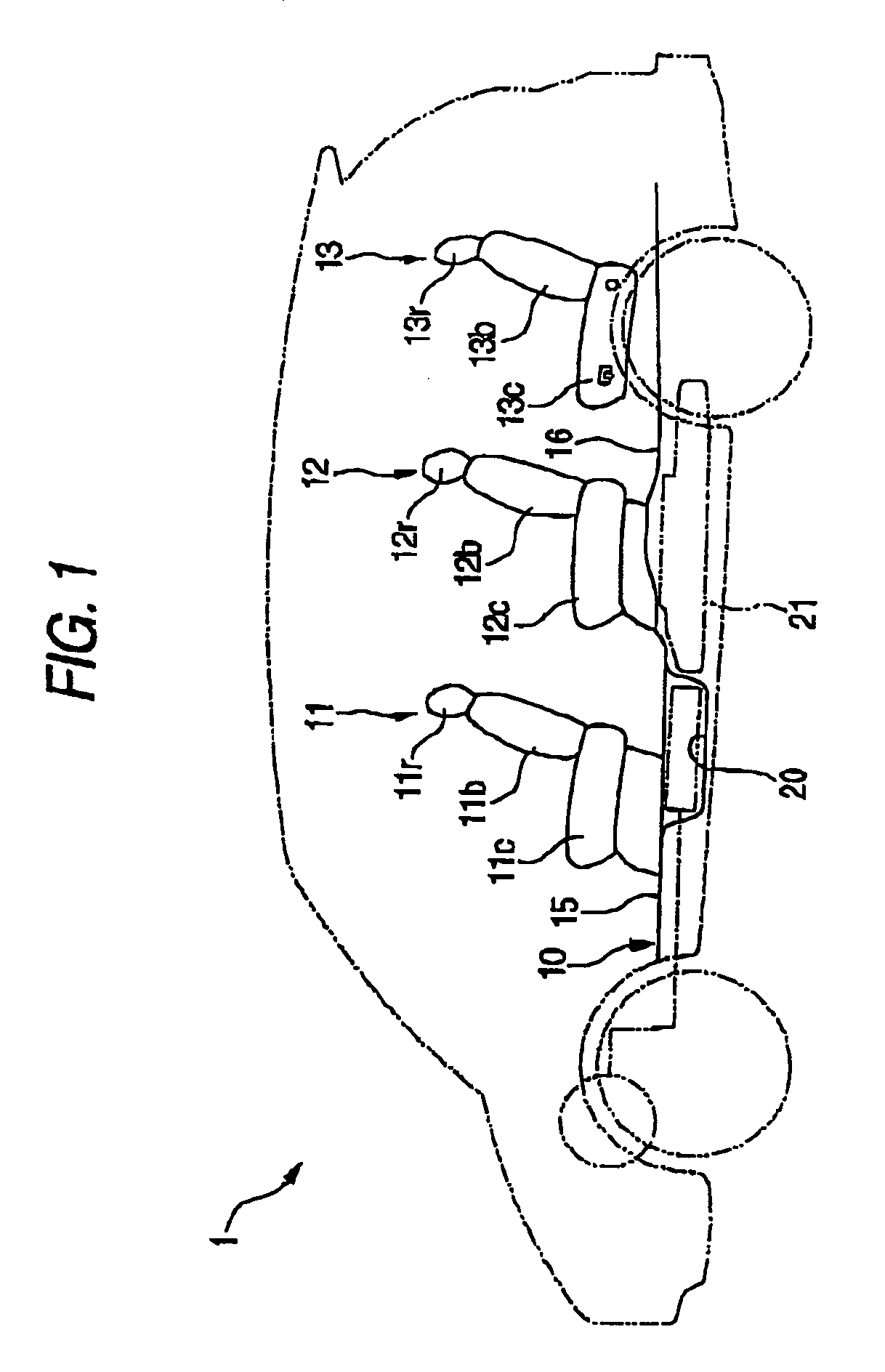
[0049]In FIG. 1, reference numeral 1 denotes a so-called two-box vehicle. This vehicle 1 has a seat arrangement structure in which three rows of seats comprising a first-row seat 11, a second-row seat 12 and a third-row seat 13 are disposed on a vehicle body floor 10 so as to be arranged in that order from front to rear.

[0050]A first floor 15 on which the first-row seat 11 sea...


PUM


Abstract

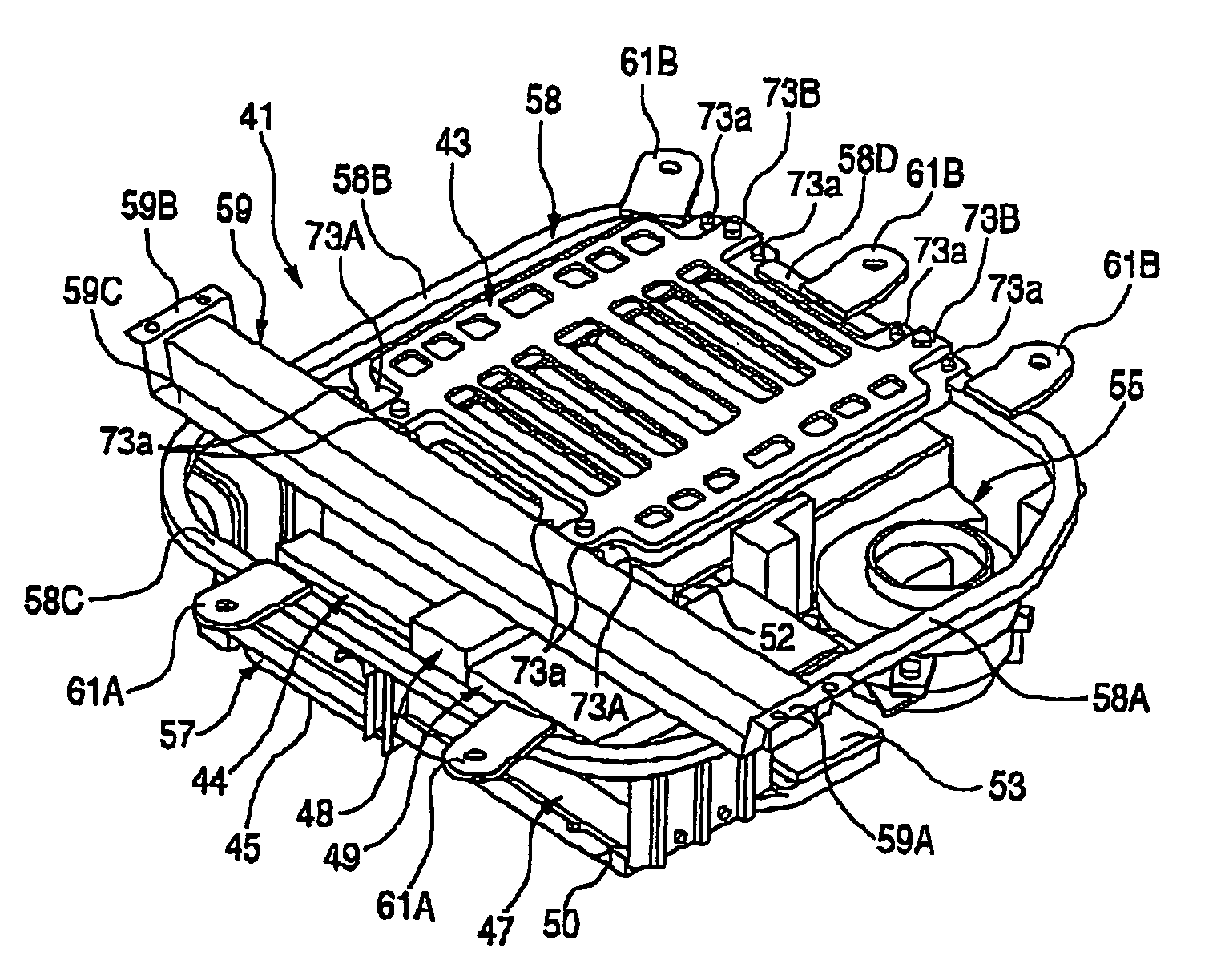
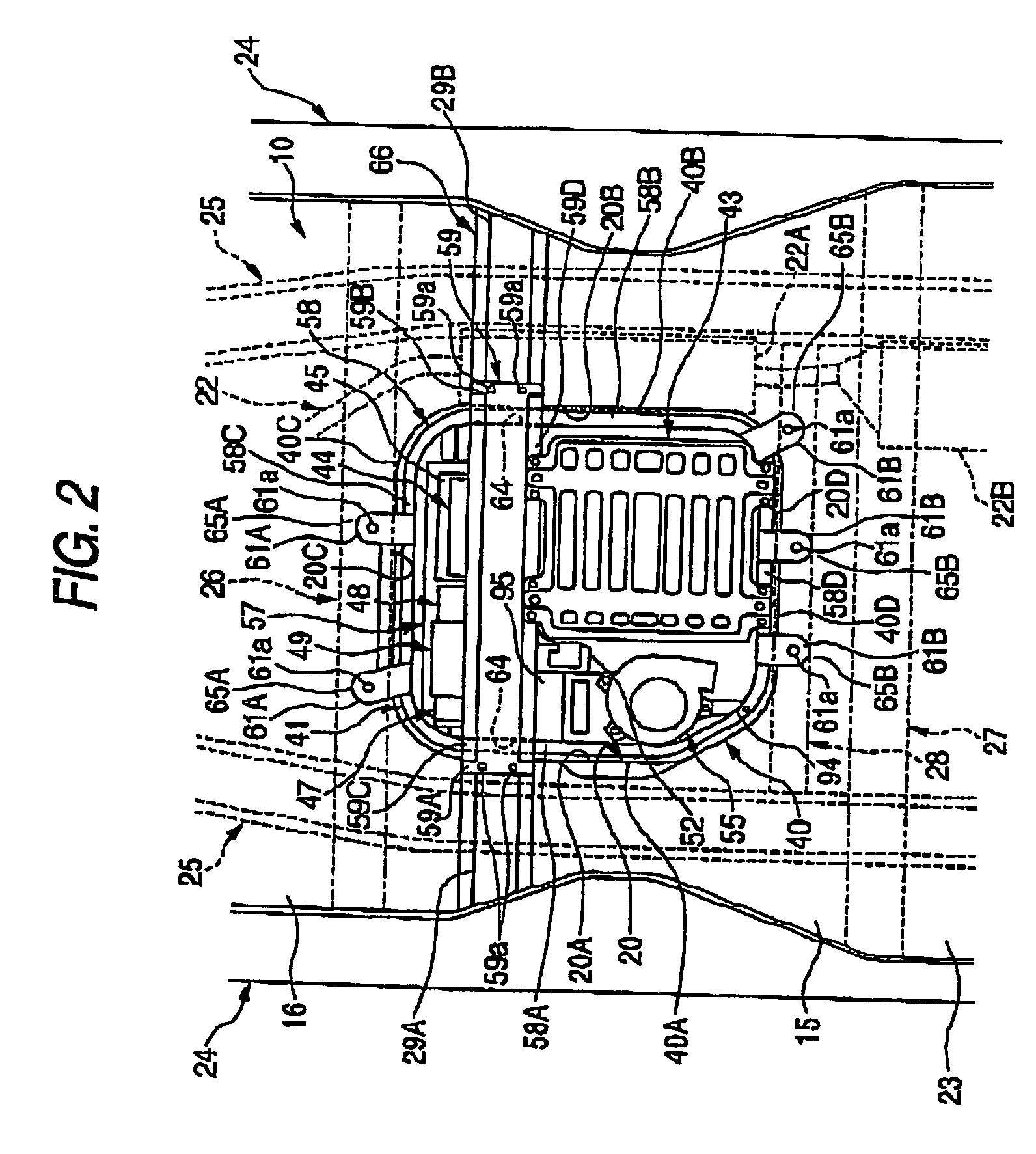
A high-voltage equipment component is disposed in a recessed accommodating portion which is formed on a vehicle body floor in such a manner as to be recessed downwardly. The high-voltage equipment component is accommodated in the recessed accommodating portion in a suspended state via a sub-assembly frame which is supported on the vehicle body floor. A heat insulating member for forming a flow path for allowing cooling air to flow towards the high-voltage equipment component is interposed between the high-voltage equipment component and a bottom portion of the recessed accommodating portion.

Description

BACKGROUND OF THE INVENTION[0001]1. Field of the Invention[0002]The present invention relates to a structure for installing a high-voltage equipment component to a vehicle.[0003]2. Description of the Related Art[0004]In a hybrid vehicle which runs using an output of an internal combustion engine and an output of an electric motor or an electric vehicle which runs only on the output of electric motor, a large high-voltage equipment component is installed on a vehicle. As a technique relating to a structure for installing a high-voltage equipment component on a vehicle, there have been disclosed structures in which a high-voltage equipment component is mounted an a lower side of a vehicle body floor from below (for example, refer to JP-A-7-156826 and JP-A-11-178115).[0005]However, in the structure in which the high-voltage equipment component is mounted on the lower side of the vehicle body floor from below, mounting and dismounting work must be carried out from below relative to the ...

Claims


Application Information

Patent Timeline
IPC IPC(8): B60R16/04
CPCB60K1/04B60R16/04B60K2001/0433B60K2001/005B60L3/0007B60L3/003B60L3/0046B60L2210/10B60L2210/40B60L2240/36Y02T10/70B60L50/16B60L58/21B60L58/26B60L50/66B60L50/64Y02T10/72Y02T10/7072
Inventor MASUI, RITSUOOHTSUKA, HIROSHI
Owner HONDA MOTOR CO LTD
Learn More